 ----- The N2DVM BLOG of projects and what not. -----
Wooooo Hoooooooooooo! Just found out my 1541U-II has shipped. I missed the last batch by 9. Had to wait about another month plus till the new batch arrived. I originally place my order in Feb 2010 but didn't pay till Aug 2010 because we were told to hold payment. I hope it arrives in the next week or so. Man am I going to have a lot to learn with this device. From all the talk, it does a lot of neat and handy tricks.
NOTE : Entered this in the blog but never Uploaded it until now. (9-JAN-2011) DOH!
I was asked for pictures of the Cardco S'More cartridge. I dug my cart out, ripped it apart and posted pictures under the Cartridges link from the main page. When I get some time, I'll pull the 3 - 2764 EPROMS and dump them and put the binaries at the bottom of the page. Big thanks to DLH of Bombjack for scanning the manual in. A link to the file located on my server is below the pictures.
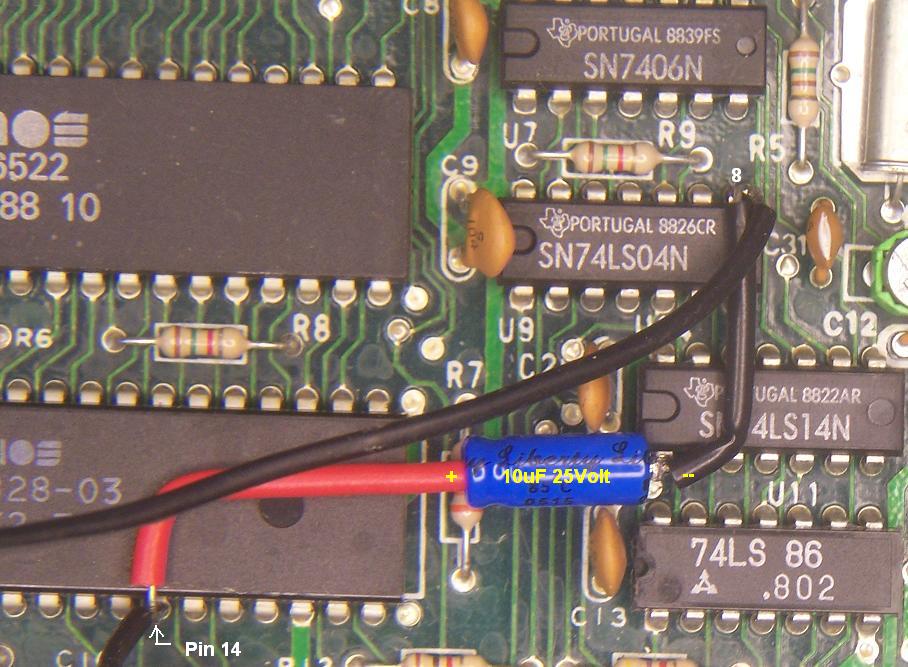
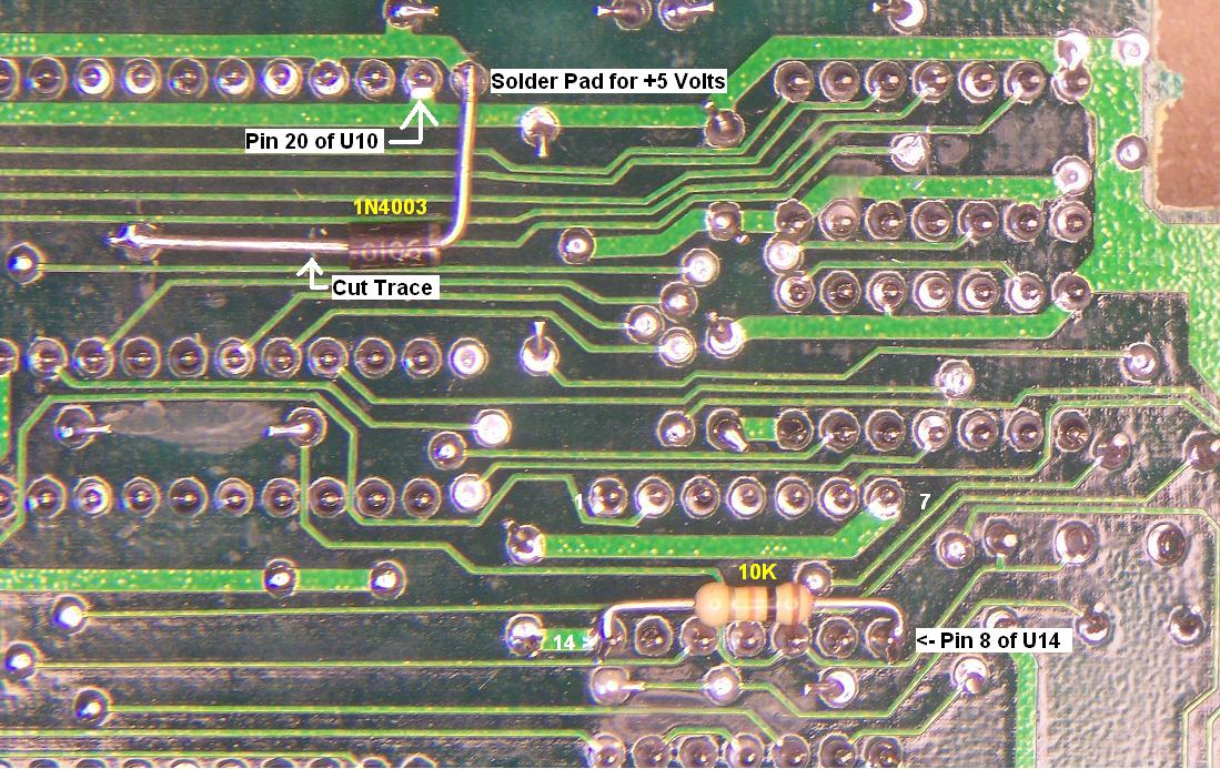
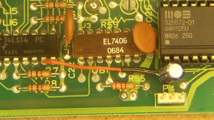
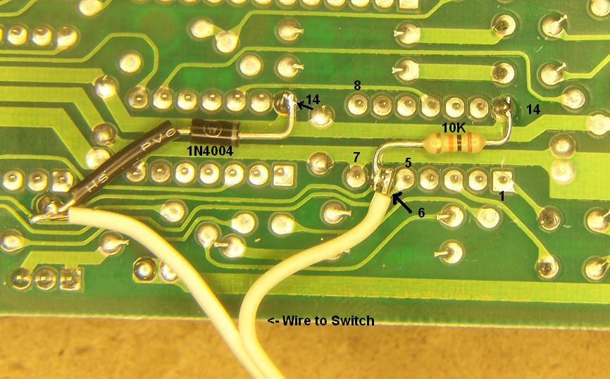
Did the Write Protect Enable mod on a 1541-II tonight, That makes one mod each for a 1541, a 1541-II and a 1571. :). The 1541-II was a little different, on the 1541 Mod, you cut the trace from Pin 6 of the 74LS14 IC, on the 1541-II, you cut the trace from Pin 8 on the 74LS04 IC. All connections that are soldered to pin 6 of the 74LS14 and now MOVED to pin 8 of the 74LS04 IC. Ray says to solder all the components to the top side. I put the 1N2004 Diode and the 10K resistor on the Bottom of the board as seen in the picture. Less stuff to "STACK" on the top side. The capacitor was to "FAT" to fit on the bottom and STILL be able to screw the board back down. The switch wires are connected across the Capacitor. The switch reconnects the TRACE that was cut to put the drive back to stock.
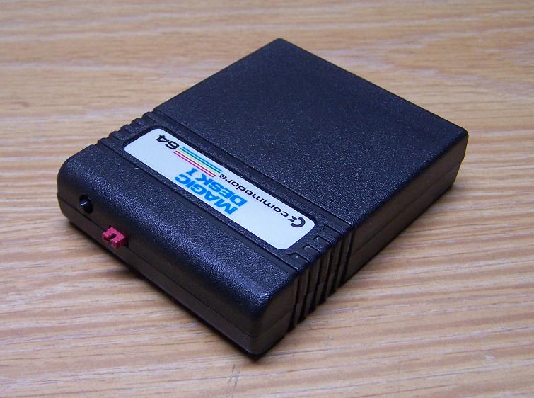
Decided to put an Easyflash board in an extra case I had in the parts box. I used a "Magic Desk I" cartridge case to do this. I didn't put the Programming LED in this cart. You KNOW when it's being programmed, really don't need the LED.
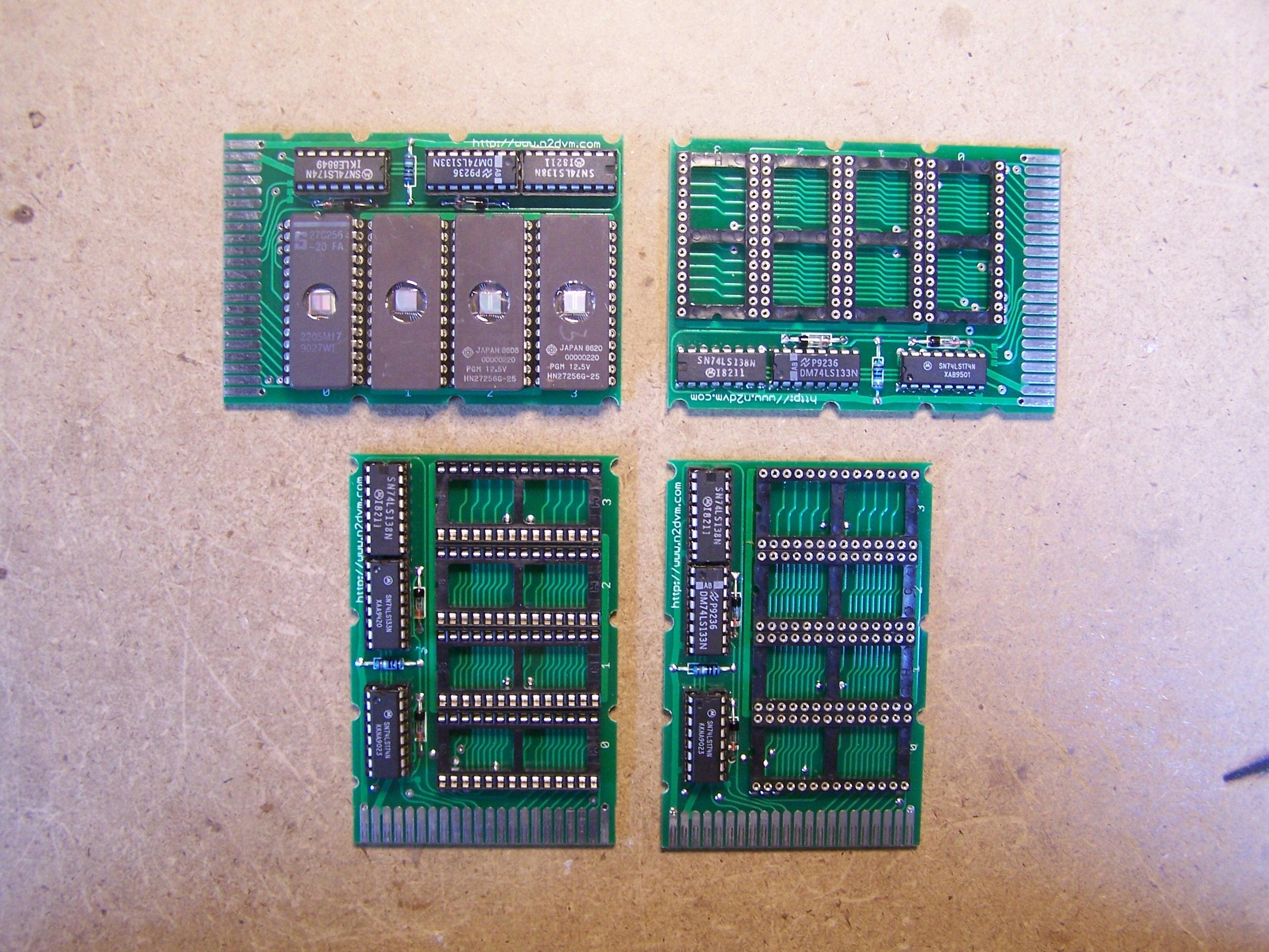
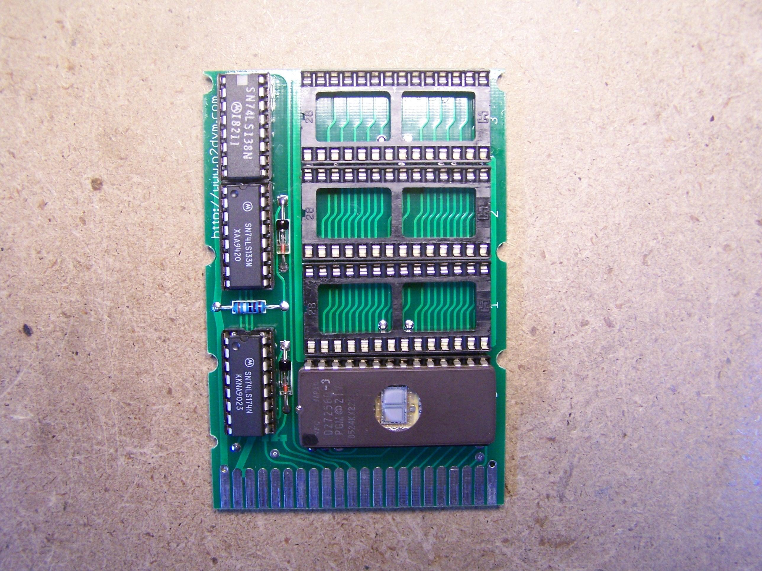
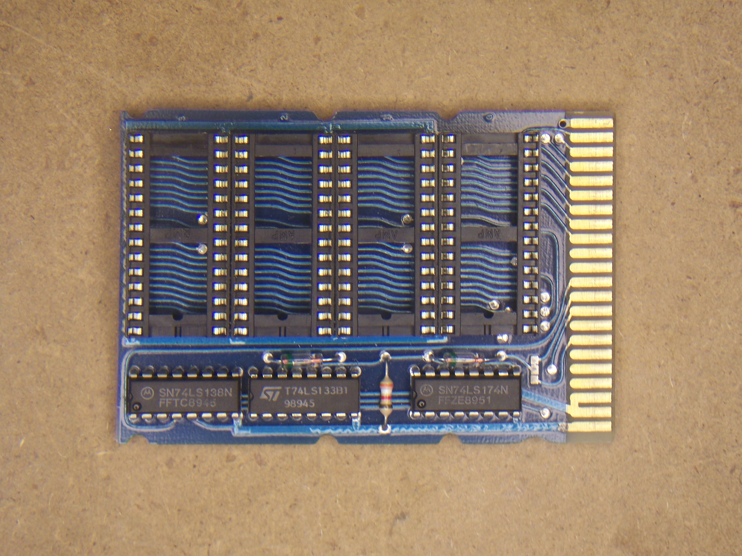
Below is a pic of the Assembled and tested Jason-Ranheim PCC-4 Cartridge clone boards. I managed to find some Binaries for this cartridge. Thanks to Rizal Acob for those. At this point, I haven't learned how to do my own. I'm working on it. Just going to take a bit of time. I HOPE to get a hold of some 27256 - 32K EEPROMS, they can be erased MUCH faster that EPROMS can. Having those will surely help me test much faster. If you have some and would like to Donate them to me, Please drop me an e-mail. Click the picture for a close up view of the boards.
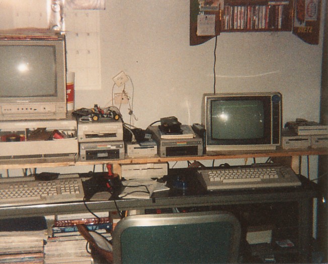
Was going through a few directories on my computer and came across the scan of a pic I took of my Old Commodore Setups. The 64C System on the left was my BBS computer. I ran a BBS called "Hells Border BBS". I was a distro site for Mirage for a little while. The System ran DMBBS v4.x, 3 - 1581's, a 71' (in 71 Mode) Main System drive and a 1541. Yup, thats right, 5 Floppy drive on that system. It also has a 256k REU for Online games. a Supra 2400 External modem, (Between the Monitor and the 1541). The BBS was a 24/365 setup. It was ran in the 315 area code. Just a note, the FLOPPY Drive on TOP of the 2 - 1581 drives is a PC 360k floppy drive. The 128 System on the left, The 1541 and 1541C are connected to it and NOT the bbs system. I later tradded the 128 for this XT. that was my first ever PC and was my first step in getting out of C=. :( It's sad but true...
The Jason-Ranheim PCC-4 CLONE Cartridge boards (12 pcs) arrived on the 3rd, Just finishes assembling one of them. I'm happy to report, Initial testing on the PCC-4 board is a Success. I used the ROM that was on the board I used to create the new boards. See the "8/23/2010" entry for a screen shot of what the cart is. I need to set aside some time and read The Eprom Programmers Handbook to learn how create a 4 EPROM cart to be sure everything is as it should be. Another Successful project in the books. Click on the picture for the LARGE Detailed photo. A big thanks to Jbevren for spotting a couple small errors in my drawing. Thats what I get for trying to do it all at once. Moloch, Thanks for the PDF PCC-8docs.pdf.
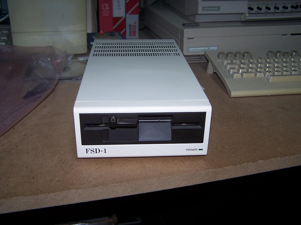
Yesterday my FSD-1 arrived that I won on eBay. The drive was dang near mint, Excellent condition, works perfect. I was reading on Ray Carlsen's website about the FSD-1. There is a text file "FSD-1.txt" that says the FSD uses the Commodore ROM as the 1541-II. "It is apparently a clone of the Commodore 1541-II REV 4 as it uses the same DOS ROM (CBM 355640-01, checksum hex 641F)" so I decided to try and make a copy of JiffyDOS for the 1541-II. I'm happy to report that it DOES WORK!
UPDATE: 01:27 10/27/2010
---------------------------
Some Information was given to my by Dragos on IRC, Thank You.
There are two different versions of the FSD-1. As far as JiffyDOS is concerned, the chips are sold for the FSD-1 and the FSD-1(V1). The FSD-1 will use a chip that has a resistor and switch wires soldered right to the pins of the chip while the FSD-(V1) uses a chip mounted on a circuit board and the resistor and wires are soldered to the board. The two are NOT interchangeable. Keep this in mind when you advertise the JiffyDOS.
Some more info found in the same thread:
The FSD-1(V1) JiffyDOS rom will not be mounted on a circuit board. It will have the switch wires soldered directly to the chip and the resistor will be soldered to pins 26 and 28. The FSD-1 which is considered to be the newer style could be with or without a circuit board. The very first JiffyDOS chips for this drive were mounted on a circuit board. The later versions of this chip did not use a circuit board. The switch wires are soldered directly to the chip and the resistor is soldered to pins 27 and 28, unlike the FSD-1(V1) which is soldered to pins 26 and 28. I'll add this info to my Blog entry. Thanks.
Went and picked up some FREE Commodore goodies yesterday, I was given a C64 Breadbin, a 64C, a 1541 and a 1541-II. The C64 is in real good shape except the keyboard overlay for "Word Writter" taped to it. Works 100%. The 64C is dang near perfect, No yellowing of any kind, best one I own so far. I have 3 now. It also had one of those Suncom Mini joysticks on it. Always wanted one of those. I plugged it in, it fired right up except there was no sound. It turned out to be the 1.5 Amp fuse inside of it. Changed that and it now works 100% also. The 1541, when I plugged it in, the drive LED stayed on and the motor wouldn't stop spinning. As I had all the 7 large IC's that were in the drive, tested and working, I started with the 6522's NOPE, still was doing it, I replaced the 6502 CPU, drive started working as it should, So I retried ONE at a time, the 6522's. One of those was also bad. It's all working perfect now. Great another 1541 for the pile. At least it's working. Thats the Important part. The 1541-II worked perfect. In Excellent condition. That makes 3 of those now I THINK. I have this bad habbit that IF it doesn't work, It NEEDS to be fixed. It's fun to do and I learn from it along the way. Makes it easier to help others when they have the same problem.
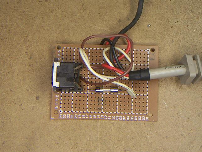
Did another write protect mod on a Really YELLOWED 1571 tonight. Worked perfect first try again. This time I put a toggle switch on the front, below and in between the POWER and DRIVE LEDs. Also, on the trace below the Blue capacitor you'll see the trace on the board that has to be cut. Info for the mod can be found HERE.
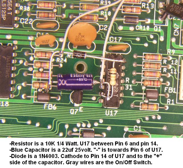
The buffer IC output line (UA1-6 in most 1571 drives) is opened by cutting a trace (conductive PC foil) on the PC board.
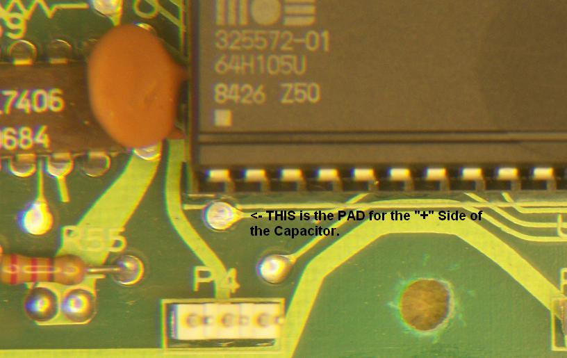
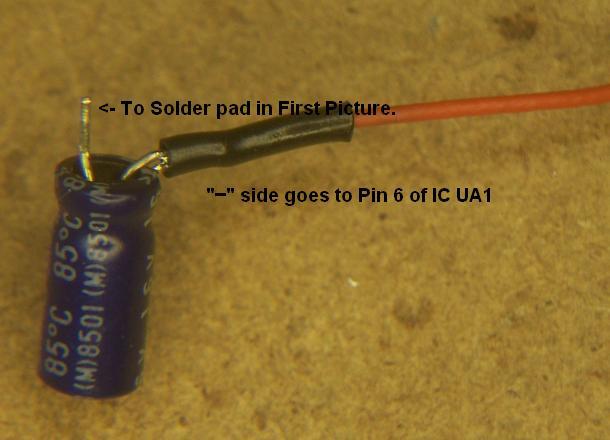
1. A 22uF (10uf - 1541) 16 volt electrolytic capacitor is installed across the cut trace ends with the negative capacitor terminal going to UA1-6 and the positive lead to the cut trace (actually to the next solder point on the board).
2. A 10K ohm 1/4 watt resistor is connected between IC UA1-6 and the +5 volt source (UA1-14).
3. A diode is connected between the positive terminal of the installed capacitor and the +5 volt supply, with the cathode lead (indicated with a line or bar at one end) of the diode going to +5v (UA1-14).
To easily disable the modification and return the drive to a normal write protect mode, a SPST (single pole single throw) switch can be wired across the capacitor and installed somewhere on the drive case. With the switch closed, drive operation is returned to normal. When the switch is open, the write protect only is defeated. These added components do not upset normal circuit functioning.
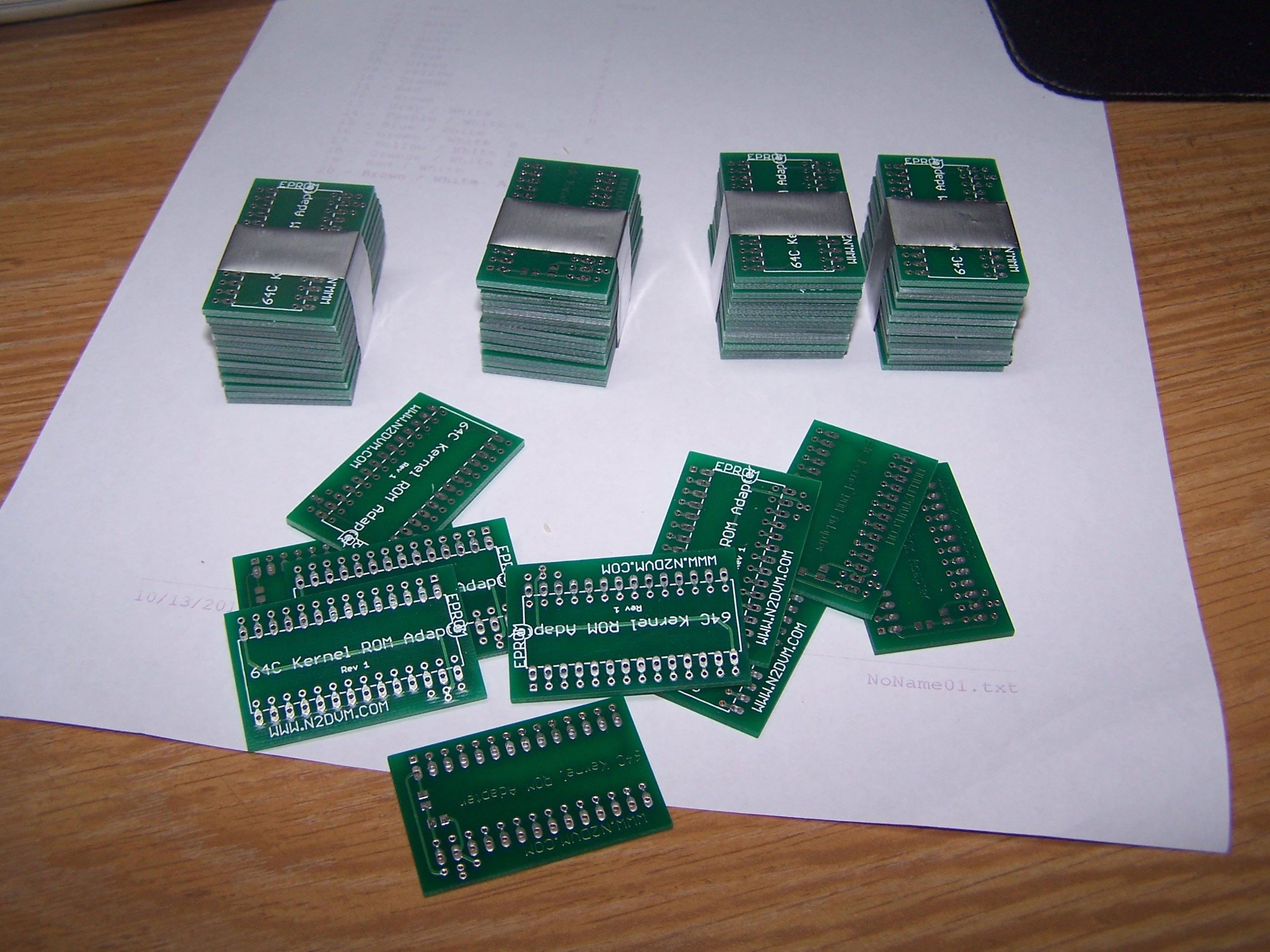
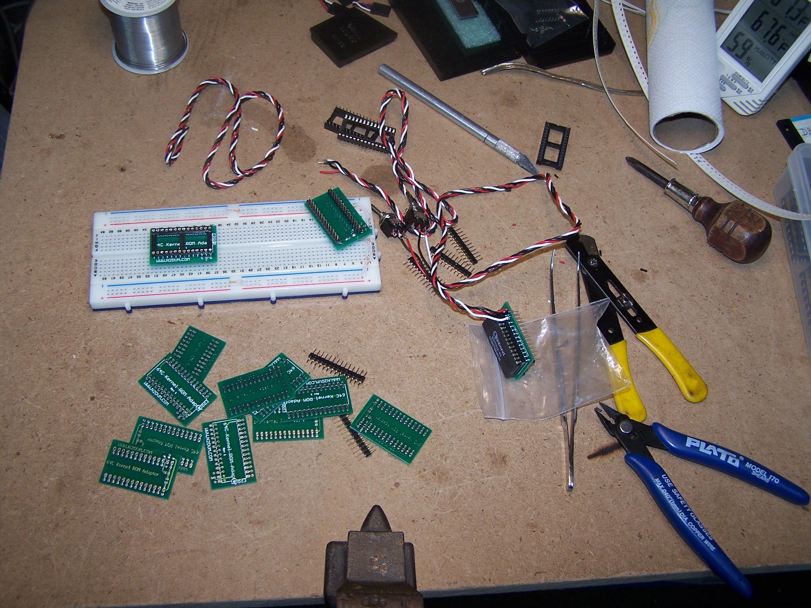
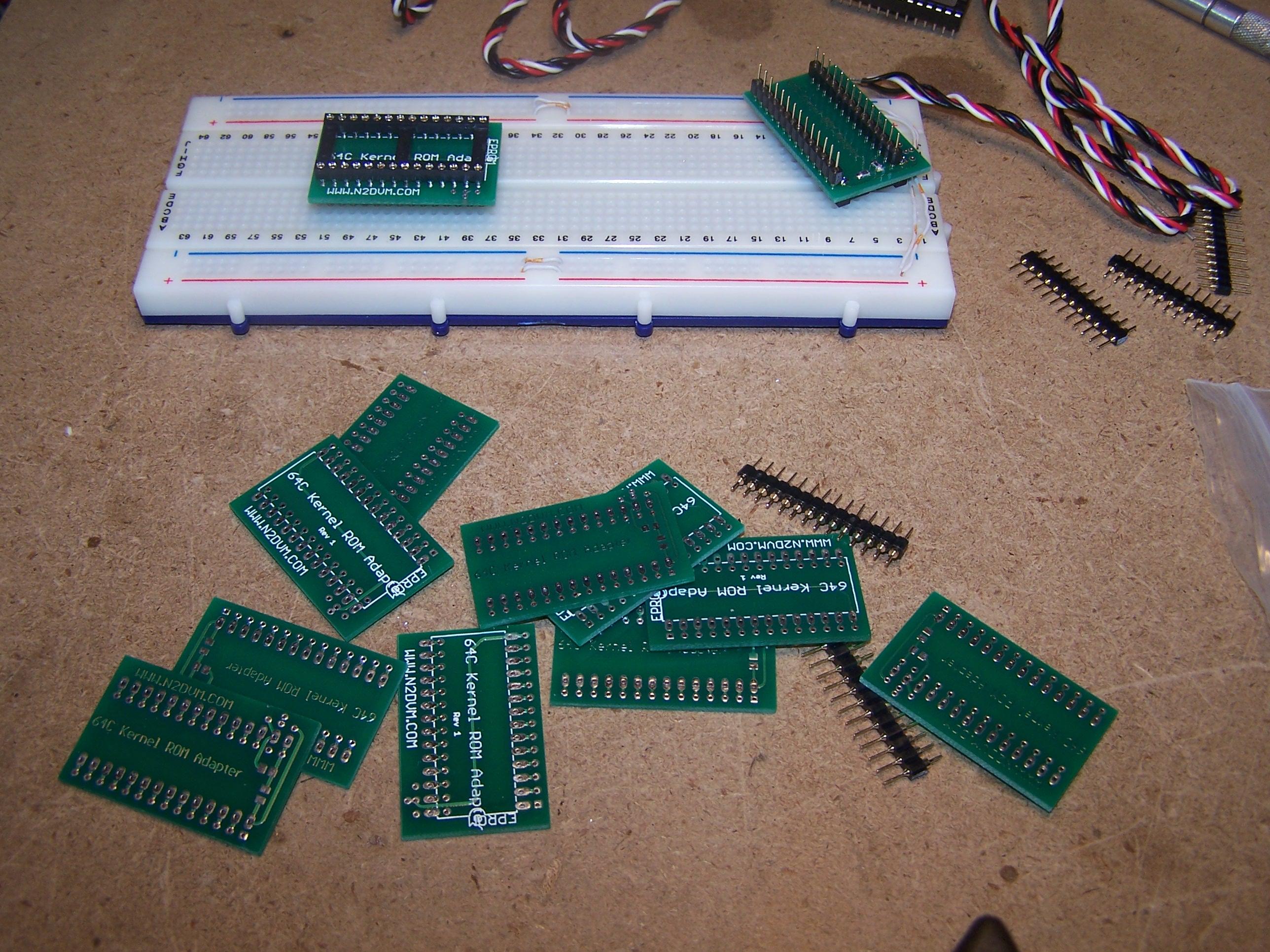
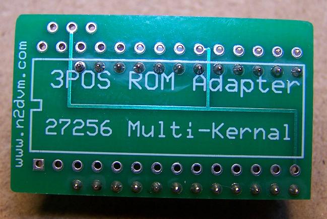
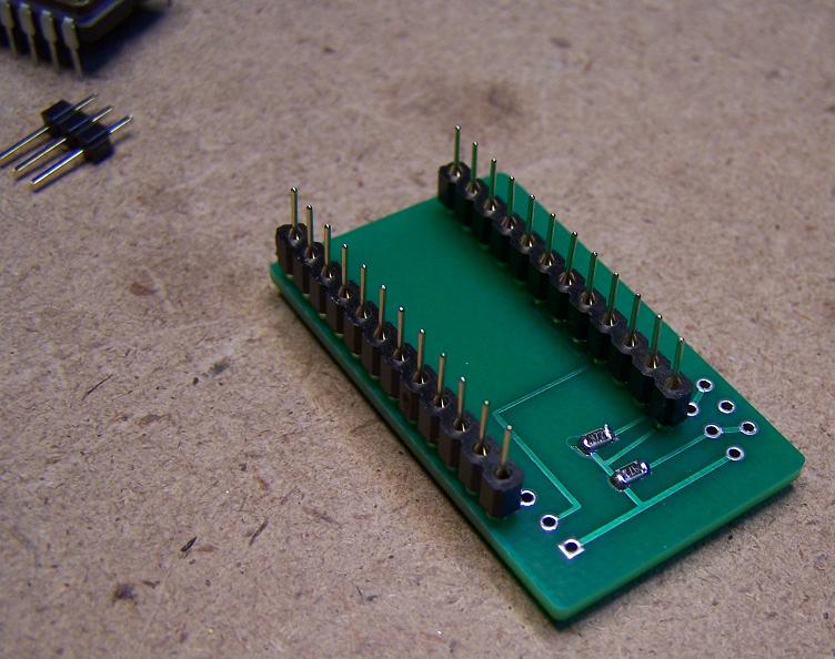
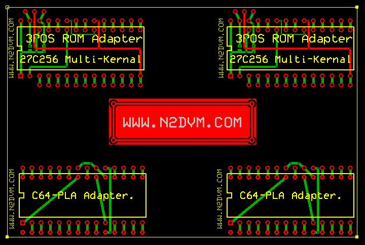
The 64C 3-Kernel ROM adapters boards arrived today. Don't look bad at all. I have already assembled and tested one. Works great. When I get all the parts together I'll get a price on them and start selling them. This batch of boards were cheaper than the C64 PCB's. I WILL be selling some of the boards with the SMD resistors already soldered on them and the Programmed EPROM is someone wants to assemble them themselves. All you'll need is some Machine Pin Headers, The SQUARE pin headers will NOT FIT. A 28 pin IC socket if you want to go that route, wire and a 3 position switch. Right now the major factor is buying the 27C512 EPROMS. I was going to use OTP (One time programmable) PROMS but it seems that EEPROMS are about the same price at least on ebay. If anyone has any info on EPROMS, please let me know. I am programming these with the same Kernels as the C64 adapter, Stock, JD & Autoboot Kernels.
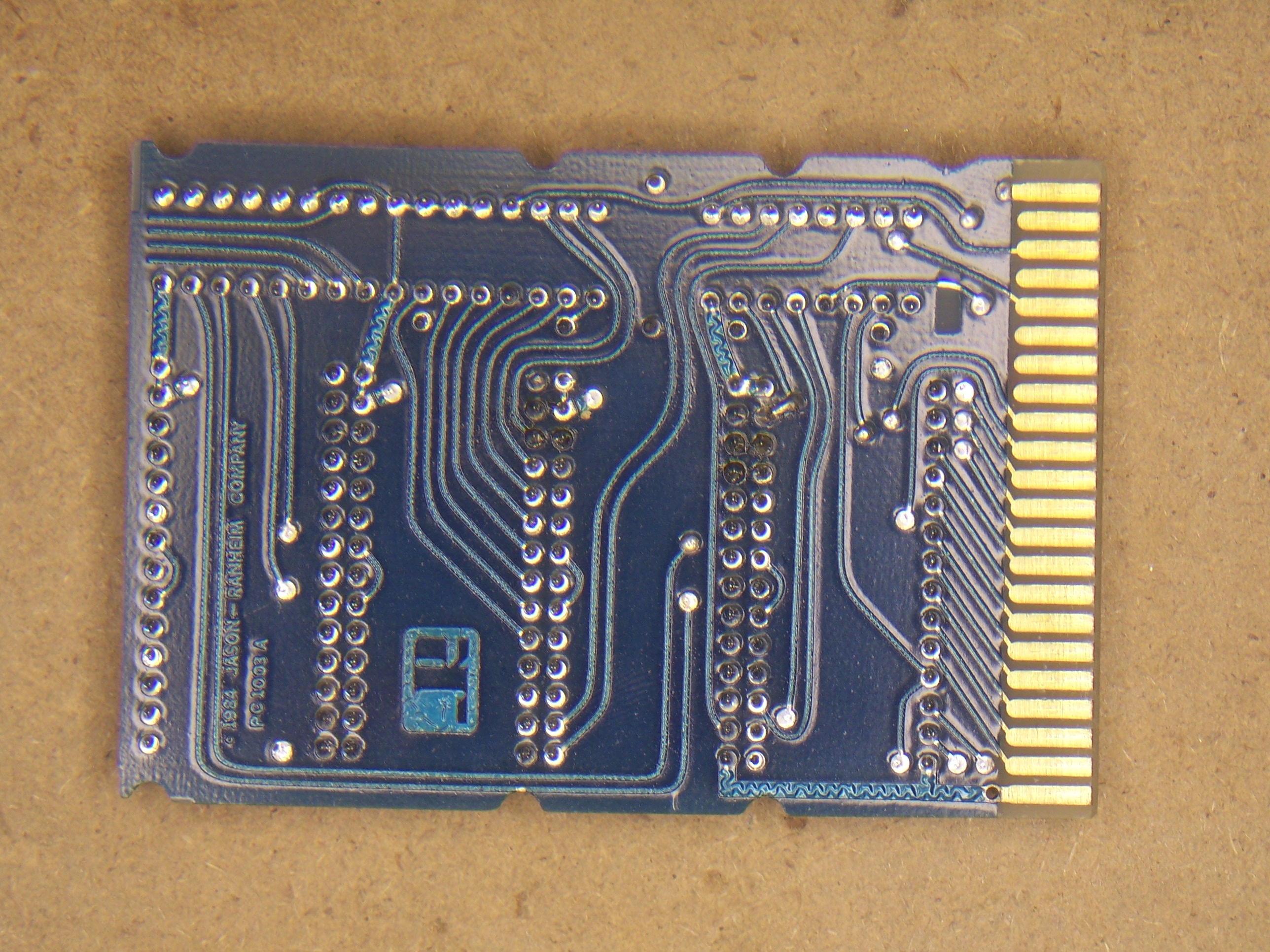
The redraw of the PCC-4 PCB is complete. I'll do some double checking in the next day or so. The one thing that took a little time was drawing the outside contour of the board. The Jason-Ranheim boards don't use the stock "Hole in the Middle" of the board as you can see in the pictures below. I believe I have them in the proper place. If not I'll have to "Tweak" them with a file.
Hmm, what have I been working on, well, I have 64 - 64C 3 Kernel ROM boards on the way, Being produced as I write this. Can't wait for those to arrive. I'll have to solder the SMD 47k and 4.7k resistors on them when they arrive. Of course I need to test one BEFORE I go through all of that of course. At the current time I don't have a SET price. I still need to order the 27C512-64K EPROMS, Switches Etc.. I'll post the info here when I'm ready to sell them. I will ALSO be selling some of the blank boards (with resistors soldered on already) You provide your own parts. (EPROM, Pin headers, Switch and IC Socket)
At this time, I have stripped a Jason-Ranheim PCC-4 Bank Switching cartridge. I am redrawing them using the EAGLE PCB Layout software. I am using the FREE Edition. You can make a MAX 80mm x 100mm / 3.1500 x 3.937 2 Layer PCB with it. So far it has been great for what I want to use it for. I have my boards made by customPCB. The last set of boards I got were perfect, just as they were drawn. Below is the pics of the PCC-4 board. Full size pics - TOP | Bottom
A bunch of years ago I read the book "Rendezvous with Rama" so of course when I seen the game by Trillium on eBay awhile back, I had to have it. Lastnight I was browsing the WEB wasting time as always unless it's C= related of course, I found a Walk Thru (Cheat) for the game. So for the next 4+ hours thats what I played. If you want a cracked copy of the game, Look HERE.
I'll be doing the same for "Robots of Dawn" tonight. Here is the Walk Thru for it. EPYX Produced the game. If you want a cracked copy of the game, Look HERE.
I have been tinkering around with WHEELS (Like GEOS) on the 128. I have a CMD Ramlink and for the life of me I couldn't get it to work under WHEELS. I got it working perfect under GEOS 128 v2.0 though. I select "disk" on the menu bar at the top of the screen then select "swap" it was showing spare drive letters I could change the current drive too. BUT No matter what, I couldn't figure out HOW to make the ramlink work. Lastnight I was in bed thinking about it and what came to mind was since the Commodore can have 4 devices, 8 - 11, I thought that MAYBE I need to change the Default device number in the Ramlink to one of those. The default Ramlink device # is 16. Sure enough, that was what it took. the first drive is #8 (1581), the second is #9(1571) so I changed it to 11 and fired up WHEELS. When WHEELS started, it shows the Ramlink as Drive "C" on the desktop. I created a native partition on it so I could use all of the 16MB of the installed RAM.
Found a copy of WHEELS for the 128 but it's in D81 format. I wanted to use geoBEAP under GEOS to create the disk. One problem, the D81 file was larger that an 800k 1581 floppy. I said HEY! Why not put it on the Ramlink and do it from there using my uIEC, NOPE! All I had was 1581 Partitions, same problem when it came to the floppy. (This was before I knew about creating one LARGE NATIVE RL Partition). DLH of BOMBJACK told me about a program called 1581disk.exe. It's used to Create or write D81 images. You also need a file called fdrawcmd.sys. It's a drive that will allow you to write to the 1581 disks. 1581disk WON'T work with out it so be sure to grab BOTH of the files. Thanks to DLH for the Info. It worked perfect. The WHEELS Disk fired right up in the 1581 on the 128-DCR. :)
Awhile back I had problems with a Commodore 1902A monitor, for no reason it would cut out on me, I would have audio but NO picture. I was told it may be a cold solder joint on the flyback transformer. Today I had the time to pull the monitor apart, I wanted to pull the entire PCB out of the monitor, to many wires, some were soldered direct, others had plugs on them. I did manage to pull the board out enough so that I could unsolder some of the RF Shielding from the bottom of the circuit board. I was able to unsolder it enough so that I could get to the pins of the flyback transformer. I was able to resolder the pins with a soldering pencil with out shorting anything out. I put it all back as it was. I took pictures of all the connections just to be sure I put it back together correctly. Put the cover back on and plugged it in, no magic smoke so that was good. I hooked it up to my 128DCR and fired it up. It's working so I must have done something right but then again the flyback transformer may NOT have been the problem. We'll see. I'll use it for awhile and see what happens.
Got to playing with the CMD Ramlink tonight under Geos 128 v2.0, Followed the instructions for setting up the Ramlink under Geos. a copy of the manual in PDF format can be found Here Thanks go to Vanessa for scanning the manual in for the C= Community.
When Geos is setup according to the RL Manual, there will be an "81 Ramdisk" icon on the desktop, you can't access it "AS IS" what you have to do is SWAP it with either "A" or "B" drive. Drag the "81 Ramdisk" icon ON TO the "A" or "B" drive, the Ramlink will NOW be the A or B drive, which ever you dropped the "81 Ramdisk" onto. I left the Ramlink set as default device #16, it worked so no reason to change it. After you do this, you can now use the other drive to copy files from the disks TO the Ramlink.
When I setup the partition on the Ramlink using the "RL/RD GEOS SETUP" program located on the Ramlink utilities disk #2, I set it up using Menu selection #6. (6) 512K DACC (RAM 71) + 1581 PART. Not sure if this is correct but I had to start somewhere, and it worked.
As most of you know, I LOVE my Easyflash cartridges, Would you like to WIN one? Check out www.cbm8bit.com I just learned of this from "ZAP" on the #c64friends IRC channel.
Register and submit an informative article on any Commodore 8bit Computer Topic including Games, Device's, Scene, Project's, Site's, People, etc. Someone will win an EasyFlash Cartridge Kit, Winner will be notified at cbm8bit on the 30th of September. Contest ends on the 30th of September. Voting on articles starts 26th of August.
Next month it will be a 64Nic+ I've been told.
Another Idea popped in my head, Why not make an Adapter for a 128 PSU to a 64 Power plug instead of cutting up a working 128 PSU. I already had the Square DIN from a couple dead C128's. Al Anger sent me a box O' Goodies that had the 4 pin C64 Power supply plug in it. I mounted the 128 DIN plug on a piece of PERF board and soldered up the wires from the 64 cable to it. Being this is the first time I ever did this, took me a bit to figure what pins went to the 9v AC and the 5v DC. After I figured it out, I soldered up the wires to the DIN plug, then took a working C64 PSU and compared the voltages to be SURE they were wired up correctly. I actually got it right on the first try. Plugged the 128 PSU into the adapter, plugged the 64 plug into the Test Bench C64 and flipped the switch. Got a nice Blue screen. :) Below is a pic of the adapter, kind of ruff BUT it's a "Proto-Type" thats the way they look...
Was talking with a friend today as was asked if I knew anything about doing a 1541 Write Protect Disable Mod. Of course I said no and then was given a link to look over. It was from Ray Carlsens website. This was a great help. I followed the instructions exactly, worked PERFECT on the first try. Ray, thank you again. Below are some pictures of what I did and HOW I did it.
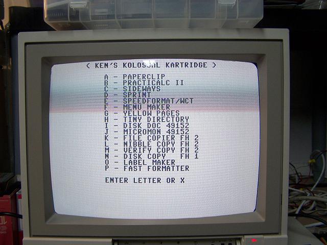
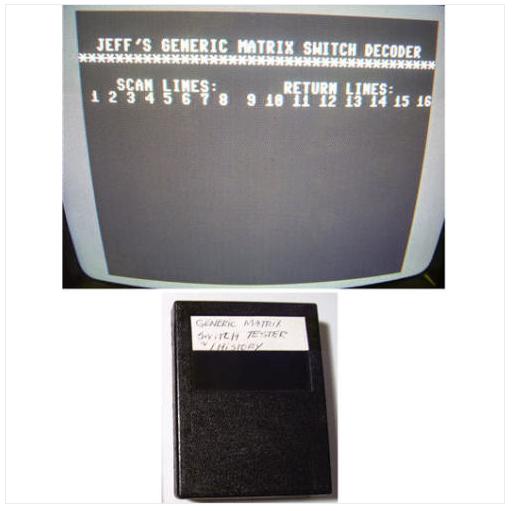
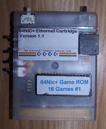
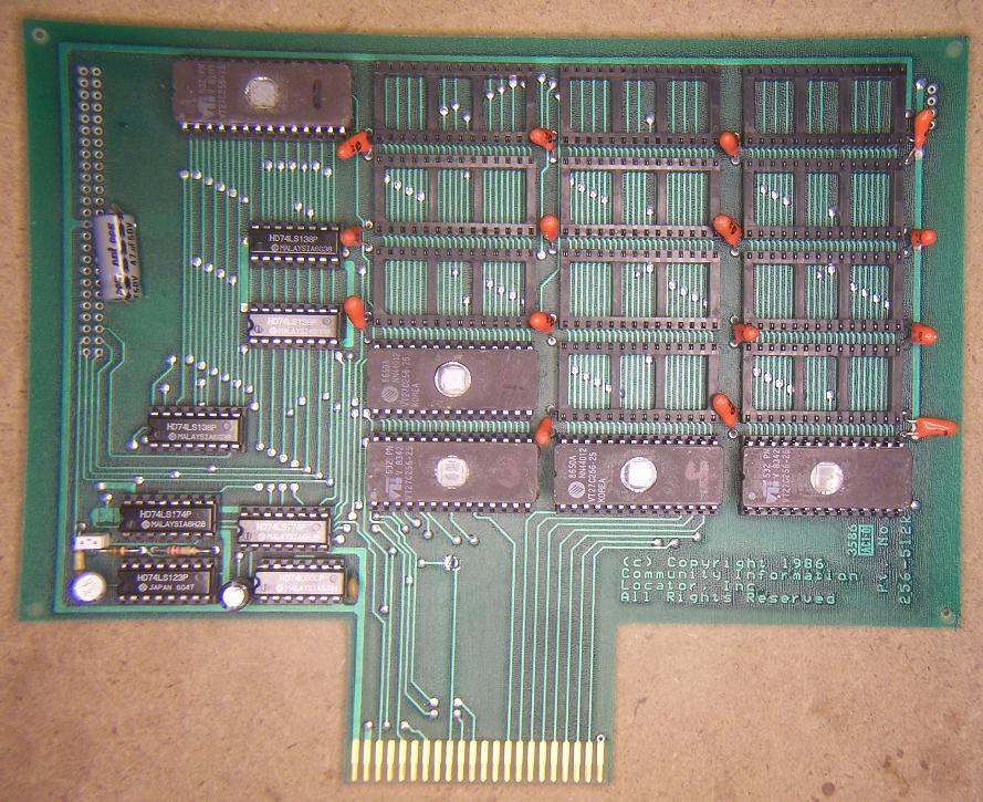
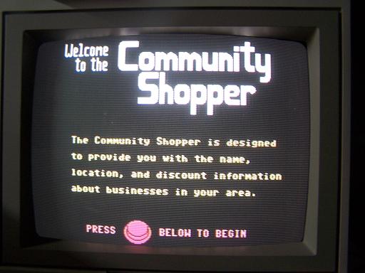
Today a package arrived from an ebay auction. There was another cartridge on there but I lost that auction. If anyone knows who won this, please have them contact me. Below is a picture of the cartridge as well as of the screen. The picture is from the the guy that posted the auctions. Here is a link to the Binary file of the ROM from my cartridge.
Been working on an Eprom for a 64C 3 Kernel ROM adapter. The C64 board is a 28 to 24 pin adapter, the 64C board is a 28 to 28 pin adapter. With a little help from Jim Brain, I was able to figure out what pins went where and how to bank switch them with a 3 position toggle switch. The C64 version uses a 27C256 - 32K Eprom, the 64C version needs a 27C512 - 64K Eprom. The pinouts are different for a 27C512 Eprom vs a 27C256 Eprom. I am currently working on a circuit board for the adapter. When I get some money saved up, I'll have some prototype boards produced and give it a go. Righ now I have an Eprom & IC Sockets all hacked up but working. I found a place that makes some nice boards called CustomPCB that will be making them.
I managed to finish up my "Disk Archiving" project. I have archived over 1600 Disk sides. When I get a moment, The collection will be placed on my FTP server in the Collections directory.
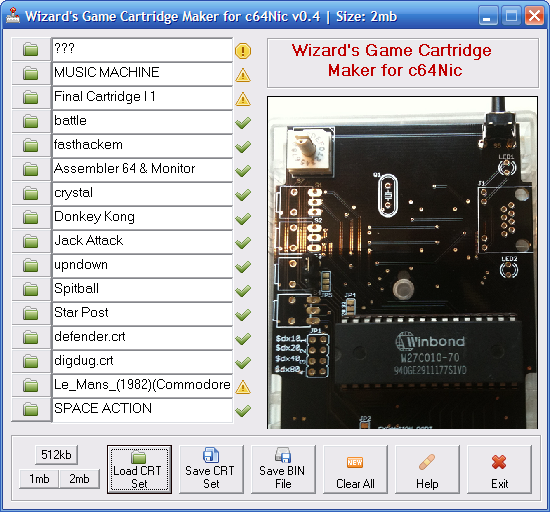
Have you been hearing about the Game roms for the 64Nic+ Ethernet Cartridge? Wanted to make some of your own but don't know how? Been thinking that you would never be able to do it yourself? Well, That's about to change. WizardNJ of the #c64friends IRC channel, has created a program called "Wizard's Game Cartridge Maker". This program can import .CRT files, strip the information that makes it a .CRT image (First 40 bytes) and turns it into a binary image that can be combined with other files to create a 1mb or 2mb image. This image is then programmed into an eprom. Currently, it takes a little work to do this with a Hex editor but this program will change all that. Stay tuned for updates. At this time, that's all I know.
For the most part, I've completed my disk archiving with Warpcopy. Unless I find any more disks, I'm at 1658 disk sides completed. I skipped over all the Gazette and Loadstar disks. They are already out on the internet. Sure saved me a lot of time there. I will be placing my archive into the Collections Directory of the FTP server this weekend. I created text files with 64Lister so the collection can be searched through with a plain text editor.
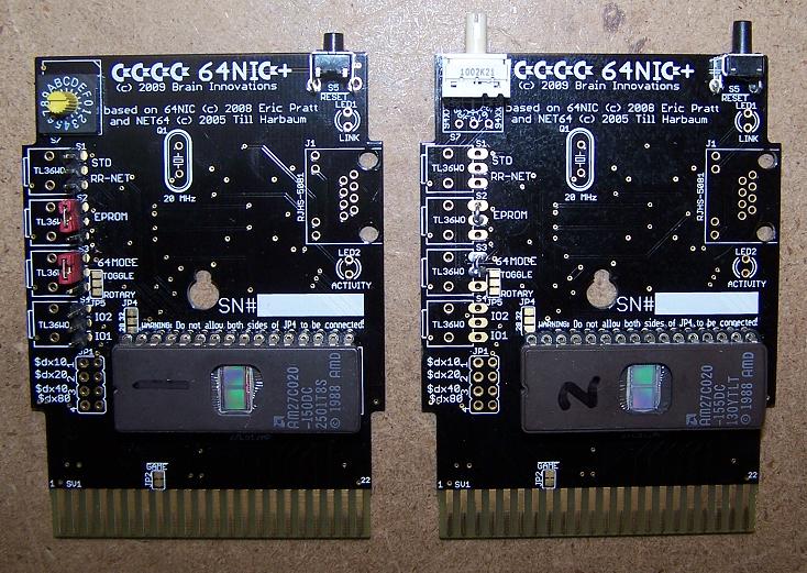
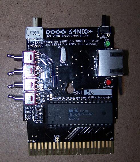
Was finally able to get my 64Nic Game rom carts working. I had to solder up some 10k SMD resistors, the 0805 size and an SMD IC. Jim, Thanks for all the help and information. The IC goes on the IC3 Pad and the resistors go on R10, R11, R12 and R13. S2 and S3 need the UPPER pads shorted as seen in the pic for the board to work as a ROM cart. I wish I had taken a pic of the board before I started, ah well.. Here is a PIC of a v1 board that was done by WizardNJ,
Been archiving a bunch of disks using my 64Nic+ and Warpcopy. At the moment I'm on disk side #961 with a lot more to go. I'll probebly put my entire disk collection on eBay and sell the disks as I won't need them anymore. This is going to take way longer than I thought but when it's done, it's DONE!
I started archiving up a bunch of my floppy disks. 800-900 of them, ALL Double sidded. At the current time, I have 1517 D64's completed. I started out with a C128/1902 Monitor/ 1571 Floppy drive and a MMC-Replay cart w/RR-Net and the Warpcopy software. One part runs on the Commodore and the other part is a Windows Application.
My network gateway is set to 192.168.1.1. When you start up Warpcopy, the default IP is 192.168.0.64, this will NOT work. Warpcopy is set to 192.168.0.64 by default on both ends. I changed it to 192.168.1.64 on BOTH parts of warpcopy. On the C= side, press the "N" key and then backspace over the IP address to change it to what you want then press enter, Now the Commodore is ready to start reading disks.
Now, load Warpcopy on the PC and change the IP address to exactly what you have on the Commodore. Now your ready to start archiving. I started out with D0000 as my first disk. You can start with what ever you want. When you click on "Next Image" the number will goto D0001 and so on... IF you have a bad disk and don't want to keep it, Click on "Read Image" and start at the number it shows, of course it will ask you if you want to over write it, or you can delete it from where ever you are archiving the files too. For the Colors of the disk blocks, see the Warpcopy site link above.
For the hell of it I decided to try running TWO Commodore systems and archiving two disks at a time, you want a workout, you'll get one doing two systems. :). What I used for the 2nd system was a 128-DCR / 1902A Monitor / 1571 and a 64Nic+ cartridge. The 2nd system was configured as IP address 192.168.1.65 on both sides. Both Commodore systems were ran to a 24 port Netgear 10/100 switch as well as the PC I was running the 2 copies of Warpcopy on.
Another guy did a writeup Here if you want to read that as well..
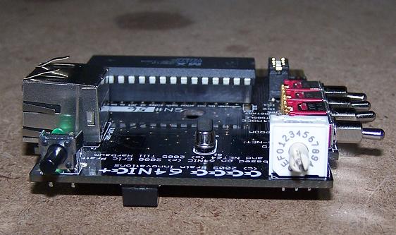
I decided to finally mod my 64Nic+ case so that it would fit with the Hex switch and Game Rom installed. below is the finished product.
Created another Game ROM for the 64Nic+. I've tested all the games, everything works great. If you would like a copy of the ROM, go HERE.
16 - 16K Game ROM #2
Switch Position / Game Name
----------------------
0-Battlezone
1-Choplifter
2-Crystal Castles
3-Frogger
4-Galaxian
5-H.E.R.O
6-Jumpman Jr
7-Jungle Hunt
8-Loadrunner
9-Miner 2049er
A-Moon Patrol
B-Ms. Pac-Man
C-Pole Position
D-Robotron: 2084
E-SolarFox
F-Toy Bizaar
And another note, I purchased these UV LED's on eBay awhile back, I decided to hook one up to 12 volts with the dropping resistor to see if I could erase an EPROM with it, I happy to report that I DID erase a 2MB UV EPROM with it. :) I put it right on the UV window and left it for about 15 minutes. Sweet.. AND the LED's are cheaper that a UV eraser too..
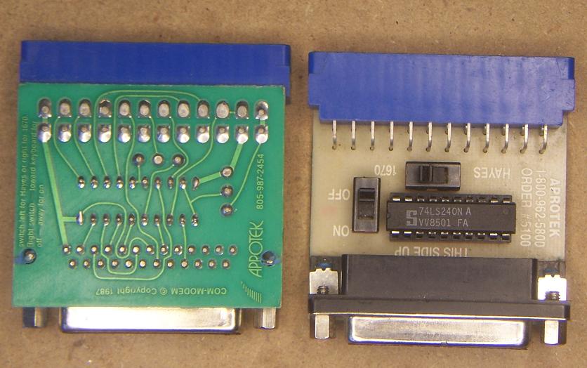
Was talking with a guy on the #c64friends IRC chat channel about RS-232 Interfaces. I had these from when I ran a BBS. I tried to find information on them on the internet, NOTHING so I figured I might as well take a good pic of them and post it. These are Aprotek model #5100 RS232 Interface adapters.
Updated some info in the 4/24/2010 entry about the AUTOBOOT GEOS ROMS.
I've posted a bunch of stuff here related to EPROMS but have never said what programmer I use. I use a Willem USB GQ-3X programmer that I purchased Here. Below is a picture of the Willem..
Worked on the first 16 Game 64Nic+ 2MB ROM tonight. Works great. I used a 27C020 AMD Eprom in my Willem GQ-3X Programmer. If you want a copy of the binary, go Here The list of games are as follows :
Switch Position / Game Name / ROM Location
----------------------
0 - Beamrider - 0003C000
1 - Congo Bongo - 00038000
2 - Defender - 00034000
3 - Dig Dug - 00030000
4 - Donkey_Kong - 0002C000
5 - Galaxian - 00028000
6 - Gorf - 00024000
7 - Gyruss - 00020000
8 - Ms-Pacman - 0001C000
9 - Pac-Man - 00018000
A - Pitfall - 00014000
B - Q-bert - 00010000
C - River Raid - 0000C000
D - Robotron - 00008000
E - Spy Hunter - 00004000
F - Wizard Of Wor - 00000000
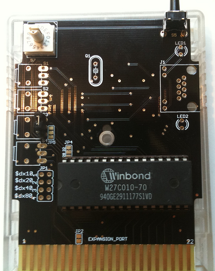
Worked on the 64NIC+ cartridge tonight. Had a talk with jim and found out the needed information to be able to use the EPROM socket on the board. Much appreciated Jim Brain for the information. The board is HARDWIRED (It can be changed with some soldering and trace cutting.) for a 1MB EPROM. I only had an MX 28F1000PPC EEPROM to play with, works perfect on the board. You can also use a 27C512 - 64K Eprom. At this time I have NOT tried the 27C512 EPROM. I'll update this entry when I do. If you have one of these boards and want to purchase the 16 Position Rotary Switch, I used Digikey Part # GH7262-ND Right Angle Switch. Currently it is $3.37 each. Also notice in the pictures the Toggle Switches positions. Won't work otherwise. You can use 8K Files on the board BUT they must be "PADDED" to make them a 16K (16384 bytes) file. I usually create an 8K (8192 bytes) file with nothing but "00" in it.
Programmed the board with 8 - 16K files. The first file, located at 00000000 of the EPROM is Switch Position 7. and the Last file, located at 0001C000 is Switch Position 0.
POS - Location
--------------
7 = 00000000
6 = 00004000
5 = 00008000
4 = 0000C000
3 = 00010000
2 = 00014000
1 = 00018000
0 = 0001C000
I was talking with Vanessa and Clocky on the IRC channel #c64friends today, we were talking about the problem I was having with a 64NIC+ Ethernet cartridge and a "FLAT" C128. There is a program called "SETMAC" that gives the cartridge a MAC address. I run it, it give the 64Nic+ an address like it should. I run Warpcopy64 I give it an IP address of 192.168.1.64. On my PC, I try to PING that address and I get the following:
c:\>ping 192.168.1.64
Pinging 192.168.1.64 with 32 bytes of data:
Request timed out.
Request timed out.
Request timed out.
Request timed out.
Ping statistics for 192.168.1.64:
Packets: Sent = 4, Received = 0, Lost = 4 (100% loss),
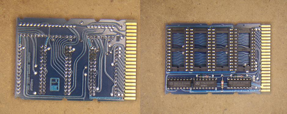
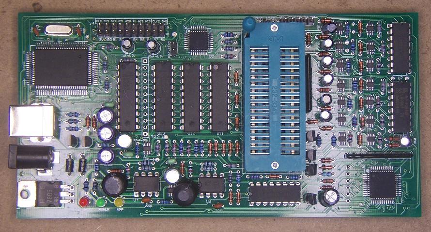
Thats NOT what you want to see. Recently I was given a "KIOSK" board from a friend. It had a small adapter board attached to the larger board. A pic of the entire board can be found Here. When I plugged the 64Nic+ into this board, and then plugged them BOTH into the C128, Fired up the SETMAC program again, loaded warpcopy64 again like before, I tried to ping it again, what I got was the following:
c:\>ping 192.168.1.64
Pinging 192.168.1.64 with 32 bytes of data:
Reply from 192.168.1.64: bytes=32 time=4ms TTL=128
Reply from 192.168.1.64: bytes=32 time=5ms TTL=128
Reply from 192.168.1.64: bytes=32 time=5ms TTL=128
Reply from 192.168.1.64: bytes=32 time=5ms TTL=128
Ping statistics for 192.168.1.64:
Packets: Sent = 4, Received = 4, Lost = 0 (0% loss),
Approximate round trip times in milli-seconds:
Minimum = 4ms, Maximum = 5ms, Average = 4ms
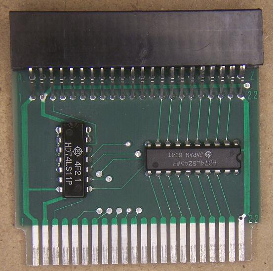
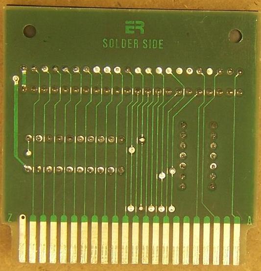
For some strange reason, I got the idea to TRY the adapter below, I think it was because Vanessa said something along the lines of "Maybe there a lot of NOISE in the circuits of the c128" or something like that. I figured maybe just maybe thats why that adapter was on the KIOSK board and without it, the kiosk board didn't work either. Well, it WORKED! As you can guess, I'm HAPPY. :) Below is a picture of the adapter board
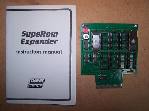
Started tinkering with the Datel SuperRom Expander board that I've had for awhile. The Manual is not really all that good at explaining some of the information so I'll just play with it and erase EPROMS until I figure it out. Today I did manage to get a program to run on it from the #1 EPROM socket. The one with the EPROM that you can see the UV window in. I programmed TWO programs to the eprom but only ONE shows up on the MENU when you boot up the board. No clue as to why this is. I'll work on it some more and see what happens. I've included a picture of the Board & Manual below...
UPDATE: Only one program at a time can be put on an EPROM for this board, that sucks. Some program do not work correctly if the Datel board is "ON" after the program starts. BLITZ is one such program, It would run but crash, if I shut the switch off and typed "RUN" it would work fine. It downloads the ROM into the RAM of the 64 and runs. When creating the ROM image, it asks you if you want the board ON or OFF, the book suggests "ON" but thats not ALWAYS the case.
Tinkered with the Promenade C1 Eprom programmer on the C= again. Learning how to program different parts of an eprom on the C=. If you want the text file I am putting the info in, go Here
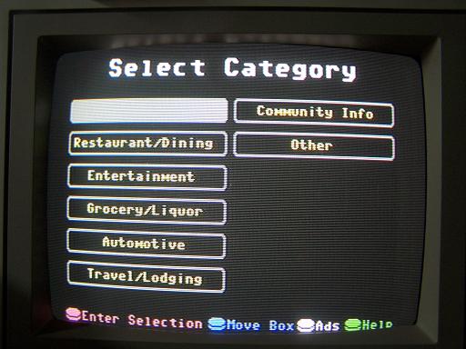
I received a KIOSK board today. It was some sort of information kiosk thing. Below is a picture of the board as well as some of the screen shots. There is an adapter from the expansionport to the kiosk board, I didn't have it on when I took the picture. I used a joystick in port 2 to control it. The picture of the board here has it. I couldn't get the board to run on a 64 but it started perfect on a 128.
And some screen shots...
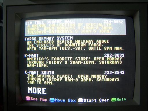
The roms on my board didn't work so I was able to grab some rom images from jbevren. Thanks for providing them on your site. My board would have been dead in the water with out them.
Programmed and Installed the JiffyDOS for the Commodore 128DCR, I used a 27C512-45 64K EEPROM for the Kernel ROM. The Original ROM was 32K and the JiffyDOS ROM was also 32K. The ROM is layed out in the following manner, 64-BASIC(8K)/64 Kernel(8K)/128 Kernel(16K) - 64-BASIC(8K)/64 JiffyDOS Kernel(8K)/128 JiffyDOS Kernel(16k). In order to access both Halves of the EEPROM, I had to install a 47K Resistor across the IC pins, 1 and 28. Pin 1 has NO Connection in the IC socket, I bent the pin out and away from the IC just enough so that when you plug the EEPROM in, Pin 1 does NOT touch anything. Solder wires from pin 1 and pin 14, this is where your switch will go. This is EXACTLY How I did it. Sorry no pictures this time. I removed the Original Kernel ROM (U32) and installed the EEPROM into the same socket, U32. It worked PERFECT on the First try, I must be learning something huh?
I also installed the internal 1571 disable switch. Info can be found Here. I did mine a little different, Thanks Vanessa for the info. I quote her here, "
It's Official! I've removed the cover of my "UNTOUCHED" Commodore 128DCR. I purchased the Binary JiffyDOS files from www.jbrain.net and am in the process of trying to get a WORKING copy of JiffyDOS installed in this machine. Once you go JiffyDOS, you'll never go back to stock. I'll post more on it later...
Welp, Jiffydos is programmed on a 27C512-45ns EEPROM, Stock Code is in the Lower Half of the EPROM, 0000-BFFF, JD is in the Upper Half, C000-FFFF, Now All I need to know is how to hook up the switch...
The Eprom works in the DCR, Both 64/128 Modes have Jiffydos now... :)
Worked on the FIRST Try...
While I had the top off, I tried a Geos 128 v2.0/1571 ROM in the extra ROM socket of the 128 computers, Worked great, GEOS Booted real fast, around 18 seconds give or take, You STILL NEED a GEOS system disk for this to work. The computer autostarts the ROM, no keys need to be pressed. Only thing is, it ALWAYS starts and doesn't let you get back to the REGULAR C128 screen. If you press the C= key to goto C64 mode, that STILL works fine. The way to get the ROM not to autoboot is flaky, so what I did was Leave Pin 28 (VCC) disconnected and put a switch on it to turn it ON or OFF.
UPDATE:
Burn one of these files into a 32k EPROM and insert it into U36 socket in
These three files contain GEOS Kernal only. You still need a bootdisk with
There are three versions:
They contain raw data, there is no loadadress.
Maciej Witkowiak
Tinkered with the 3 Kernel Rom Board using two 2 Position switches. With this configuration I was able to get 4 Kernels on one 27C256 - 32K EPROM. So I guess I should call them 4 Kernel ROM Adapters. Problem is, with the extra switch, it's added costs. Below is a picture of how I wired the switches up.
Ok, I built a 2 Switch wire harness, I tested it out. YES, with 2 switches you can have 4 Kernels on a 27C256 EPROM. Setup as follows :
--------------
I Quote Vanessa : "<+VanessaE> DM: of course. It's binary :)" LOL..
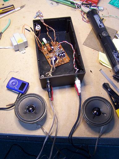
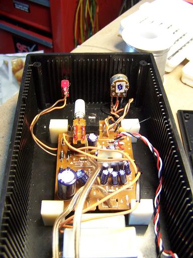
I worked on the Modded C64 again tonight, Fixed everything that was bugging me on it. One was the wires from the SID on the main board. I HAD wires soldered to the board then had test leads clipped to the wires connected to the amp. I now have an RCA plug for EACH SID going to an Stereo amplifier. For PICS of the Amp project, look farther down the page. Everything works great on this C64. I still have a couple of my 3 Kernel ROM boards For-Sale, See the description on Lemon64
Added some stuff on ebay to sell.
put up a 3 Kernel Rom adapter, the Stereo sid board, you can read about that farther down the blog and one of my PLA adapter boards. Lets see what happens. If you want to take a look, go Here.
Well, I got all the toys out, I was felt like tinkering tonight. I managed to wire up a Datasette cable to my uIEC/CF, works perfect. I also finally got time to play with the IDE64 v4.1. I think I can get used to that as well. Will take some learning but thats just the way it goes with new toys. Below is a picture of all the hardware.
Cartridge expanders or Zip Archive
Installed the Stereo SID board that Vanessa designed. It fit perfect into a C64 board. Worked great the first time. I have in my system, a toggle switch to set the second SID at different places in memory. It can be either I01 - DE00 Pin 7 on the Expansion port or I02 - DF00 Pin 10 on the expansion port. I was using a Replacement PLA that I purchased. For some reason the board worked fine at DE00 but NOT DF00. I sent the desgner a message letting him know of this problem. When I installed a STOCK PLA, all worked fine, the same goes for the EPROM PLA's that I make. I'm happy. First time I ever did the Stereo SID thing. For more information on the board, check out Vanessa's Project page. While I was doing the testing, I also tested the Sid2Sid board. Worked perfect also in both memory locations. I think I'll ebay that board as I have 3 of the "Vanessa" SID boards.
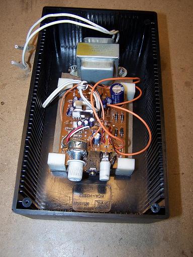
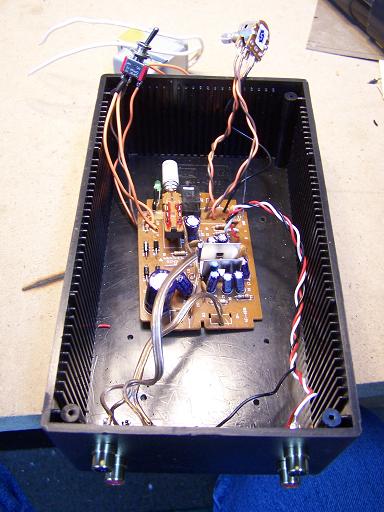
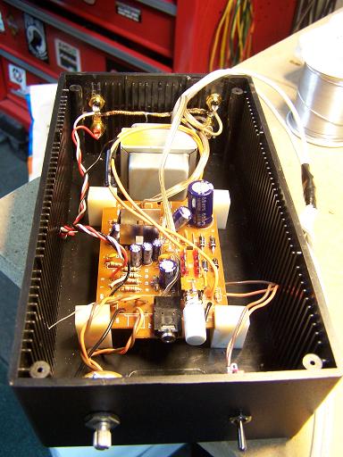
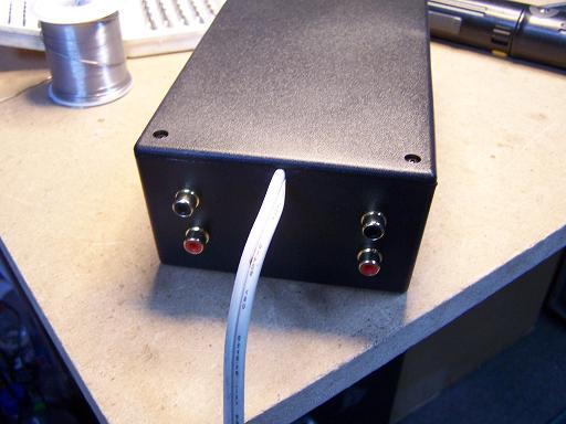
Working on an Amplifier project for the sterio sid board, It's an amp I ripped out of a pair of messed up computer speakers. It's AC Powered, 3 Watt. Bought a Project box (7 3/4 x 4 1/2 by 2 1/2 tall.) for $3.88. I will be moving the Volume control to the front of the box as well as the power button, That will be moved to a Mini Toggle switch OR a large toggle if I have one in the junk box. Well, I got it working, Now to put the Volume Control and Toggle switch in the front of the box. The board has an LED but I'm not going to bother with putting that on the front. Toggle switch will be UP=ON DOWN=OFF. Easy enough to see that...
The Sterio SID Boards that Vanessa designed, arrived today. As I type this, I'm building one of the 3 boards I have. Here is a pic of the Board Blanks for your viewing pleasure. In a C64, Take a wire off of the "-" side of C13, thats where the audio goes into CN5 (Monitor Connector) from the transistor for audio output if you want to use a Stereo amp that is. I'm going to use an amp out of a set of computer speakers.
Welp, Looks like I'm going on a 340 Mile Roadtrip to pick up a Commodore 128DCR System with 1902 Monitor, 2 - 1571 Drives, and a 1581 plus a bunch of other odds and ends. From what I gather also a Complete Collection Of Computes Gazette magazines.. Always wanted one of these systems. Figure it's well worth the $150 the guy is asking. Besides, the area he lives in is a real nice part of the state Way up North of New York state..
Worked with the program "Draco Cart Maker (DCM)" today from DCM, It's used for creating .CRT files for use with the Easyflash cartridge. I was able to get a working .CRT file today with 37 games. It worked as prescribed under VICE v2.2 running under Vista Ultimate. I was working mostly with Single File .PRG files. For the most part, they worked great. One image I created was of nothing but .PRG game files. As of this posting, I have NOT tried to program the Easyflash cart with my newely created image. If you get an Easyflash, be sure to check out the Easyflash threads on Lemon64 LOTS of good information there..
When the wiring I ordered arrives for my "3 Kernal ROM adapter", I will be putting more of them together. I will be selling some of them in the near future. At this moment, I haven't decided what I'm going to be charging for them. ALL boards will have the SMT 4.7k resistors already soldered on them.
The eight 27C512-45ns EPROMS have arrived for the PLA Adapters, I ordered all brand new ones from Jameco Electronics. I still have to program them. I also ordered a 30 pin SIMM memory socket for use with a SIMM Memory module mod that I want to try in the future. The links to the information are under the "INFORMATION" link from the main page if you want to read up on it.
Two compact Flash 4Gb cartridges arrived from Pelleas (on IRC in c64friends) for my IDE64, Thanks Pell. I've had it for a few weeks and have not even plugged it in yet. So many projects & toys and so little time to play with them all. I'll admit, the uIEC's from Jim Brain has been getting a workout that's for sure. WAY easier that making all those floppy disks with the files I need. If you don't have a uIEC yet, something's wrong with you.. See Jim's store today. :)
Worked on the Sid2Sid board tonight. I believe that it's ready to have prototype boards
made.
Played with the program "disk2easyflash_load_0.9" tonight. What it does is take a single .PRG file (Inside a .D64 disk image) and convert it to an Easyflash (TM) .CRT image that is programmed into the Easyflash cart. Nice program BUT you can only load ONE file into the image. At least thats all I could get to work. I had Multiple files in the D64 image but it only loads the FIRST file by default. You never see the other files. Would be nice to be able to do that. Somebody put a file up on Lemon64.com that allows you to put many files into a One Meg Easyflash image file. I just read about it, have NOT played with it yet. Working a lot so MOST of my projects are on semi-hold for now..
I did manage to get some of the SMT Resistors (4.7k 2each) mounted to three of the second batch (Rev.B) of the Kernal ROM adapter boards. I must be crazy for using SMT instead of thru-hole. Their a pain to find when you drop them on dark carpet. :) ahh well I like to be different, and I'm getting good at doing them by hand. Pictures coming...
I hope to start the easyflash cart build this weekend, started working some OverTime so thats taking up all my time at the moment.
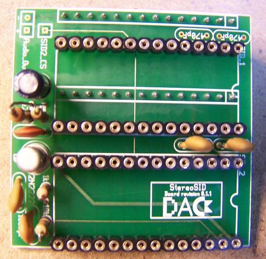
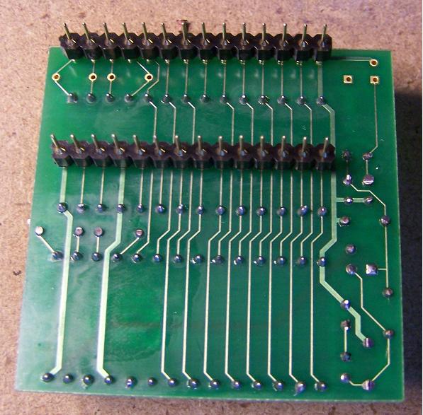
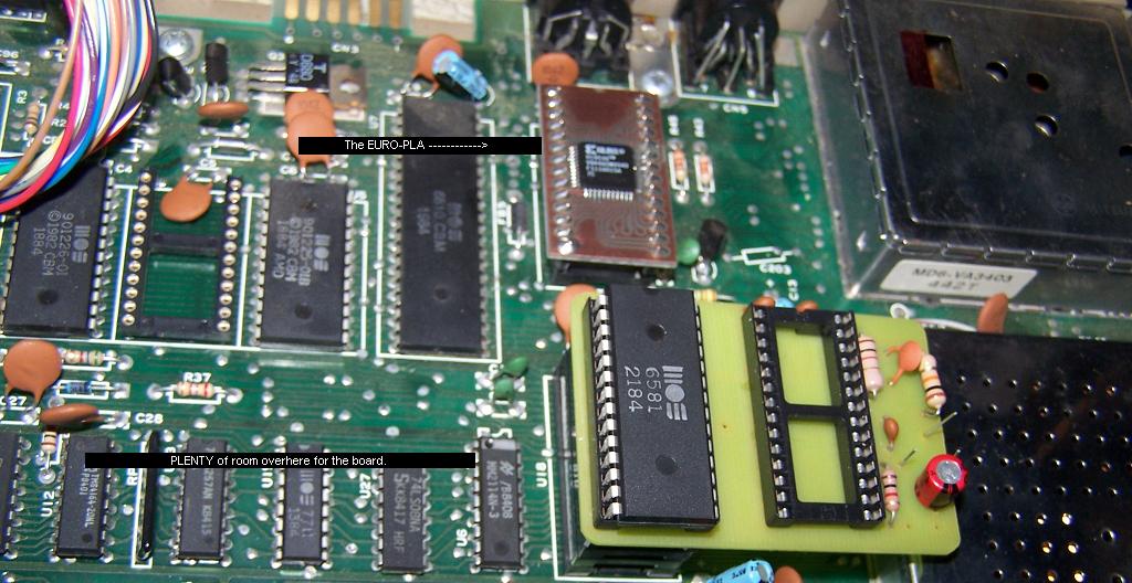
I purchased a Sid2Sid board, Started building it, and decided WTF on the layout.... Plenty of room to the LEFT side of the SID on a C64 board, WHY have the board towards the RF cage of the VIC chip! The 2N2222 transistor also hits the RF cage. I think I'll redo this board in the near future and FIX the problems myself. NOT all that hard to do.
Going to try and make a Sterio Sid board. The original drawing was done by "Thorsten Oelfke". I was given a copy of the jpg file of the layout from Vanessa. Thanks. :).
Hello and welcome to my blog, I'm going to give this a try, I will be doing this blog when ever I can. I've never done
anything like this so it will be work in progress...
What am I working on now? Been playing with a program from ExpressPCB called "ExpressPCB". It's for doing layouts for the design of Printed Circuit Boards. I am currently working on boards for the replacement of the PLA chip. The design is by Ray Carlsen and NOT me so I take no credit for that part.
Also a design that allows you to have 3 Kernals on one eprom, I currently have the STOCK Commodore C64 Kernal, a JiffyDos Kernal and an Autoload Kernal (Thanks for that Leif) all on one 27C256 32k EPROM.
02:38 4/24/2010
I found some info that was with the ROM Image.
C128. You can bypass its execution by holding RUN/STOP or C= key during
power-up or reset. It will drop you into machine monitor (exit by 'x') or
C64 mode.
at least DeskTop (but existing auto-execs will be executed before that).
Boots always to 80 column mode and not much can be done about that.
It is somewhat tuned to have centered screen on my TV set so you might
have problems with visual. Anyway, after DeskTop is loaded - press
RETURN two times and you will switch into 40 column mode.
Geos128Am1571 - american version with 1571 as device 8
Geos128Am1581 - american version with 1581 as device 8
Geos128Ge1581 - german version with 1581 as device 8
02:29 4/23/2010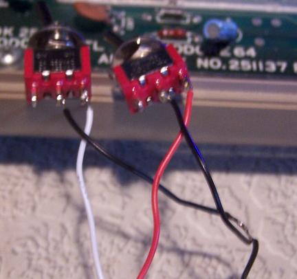
#1 = 0000-1FFF - ALL Wires Shorted. (2 Switches ON)
#2 = 2000-3FFF - Red/Black Shorted.
#3 = 4000-5FFF - White/Black Shorted.
#4 = 6000-7FFF - NO Wires Shorted. (2 Switches OFF)
04:11 4/21/2010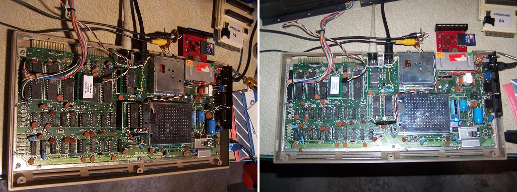
23:46 4/17/2010
03:35 4/16/2010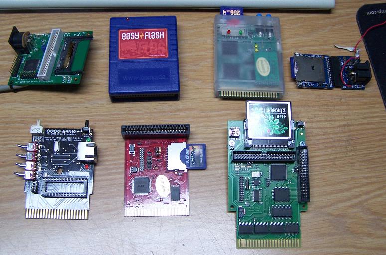
Thanks goes to Moloch for the files.
13:09 4/5/2010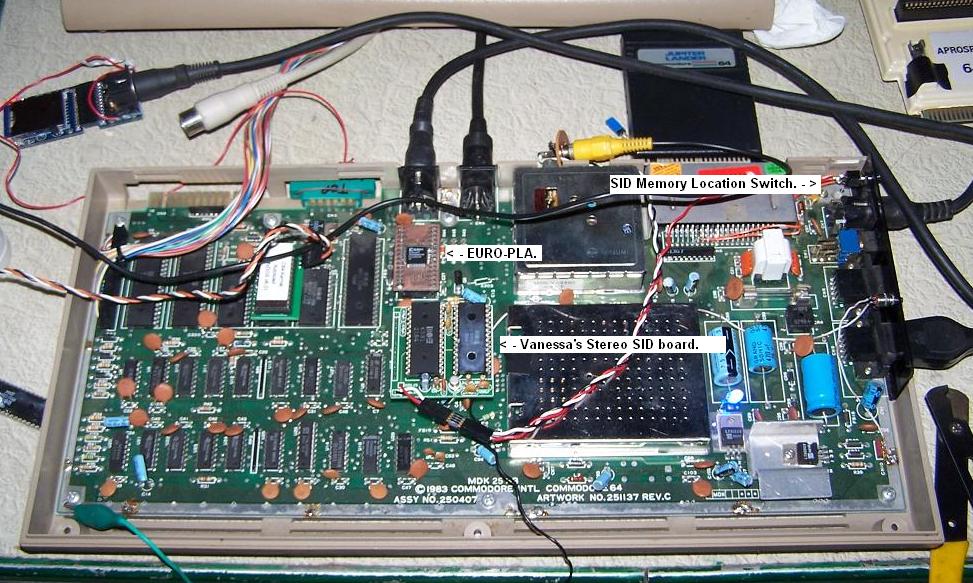
18:18 3/27/2010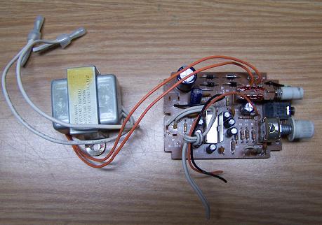

03:45 3/21/2010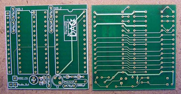
The board is approx 1 7/8 square
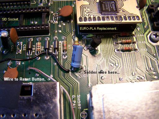
This is where you want to solder the wire too.
This is the amp I'm going to use.
14:26 3/19/2010
04:00 3/16/2010
4:00 AM 3/14/2010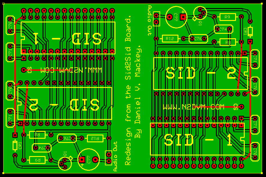
04:59 3/10/2010
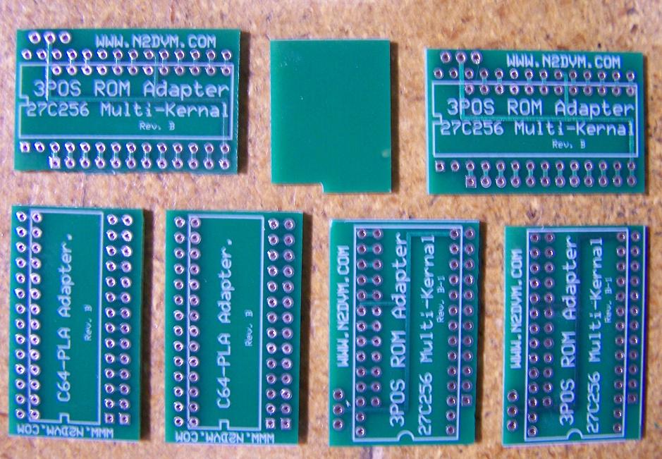
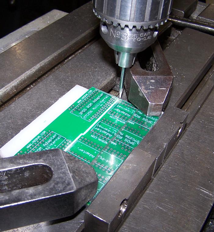
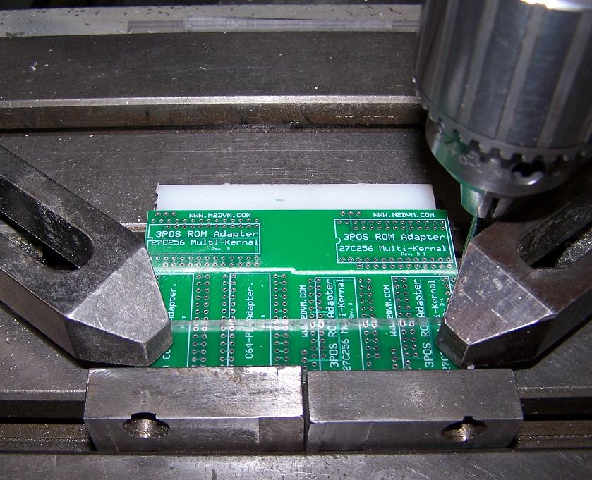
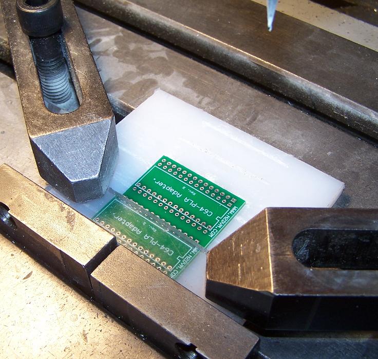
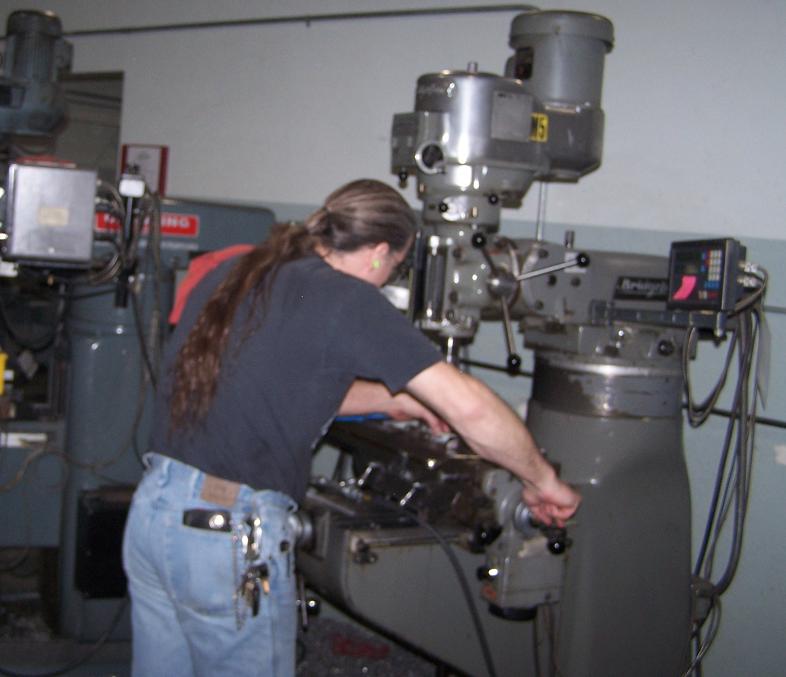
My boards arrived today, Below is some pictures of them and how I was cutting them out. Enjoy..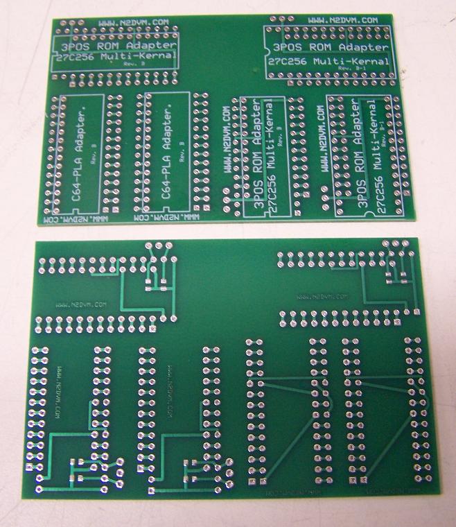
04:38 3/9/2010
Welp, I sat down tonight and drew up the Original Sid2Sid board AND my Version of that board. MY board has the board
over the logic chips and AWAY from the RF Cage. AT this point, I have NOT had the board produced. After I get through
double checking it, I will probably have 6 of them made. Here are the pics of it.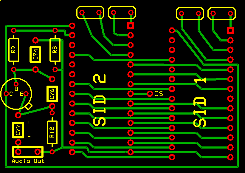
Original Sid2Sid layout.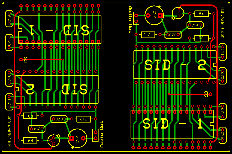
My Version of the board. 2X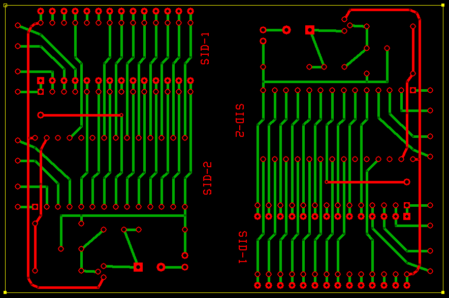
04:30 3/3/2010
Ordered up another up set of Kernal Rom adapters and PLA adapters with updates (Fixes) Should be here by the 9th. :)
00:03 3/1/2010
Just found out that my 2 Non-working C64's will be here Tomorrow 3/1/10. Then I can test out this Sid2Sid board
in the C64. I put a switch on the CS line so I can select either IO/1 ($DE00-$DEFF) or IO/2 ($DF00-$DFFF). Why?
Something else to do. :)
03:21 2/23/2010
Worked on the 3 Position Kernal ROM board tonight, Moved the wire
connection to the back of the IC. Make the board narrower. No pics but I redid the PLA adapter board also. Fattened up
the traces and the solder pads a bit. I made a mistake on the first boards. the Pin header solder pads were WAY small BUT I could still solder on them. Ahh well at least they worked, thats the important part. :)
The Kernal Rom was removed for testing. See my 3 ROM Kernal adapter board below...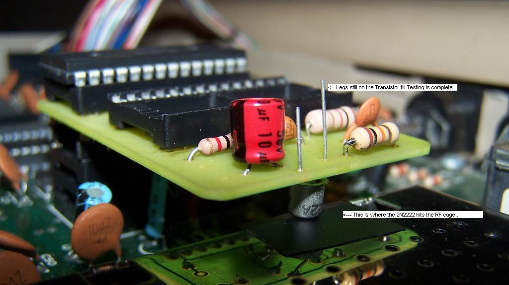
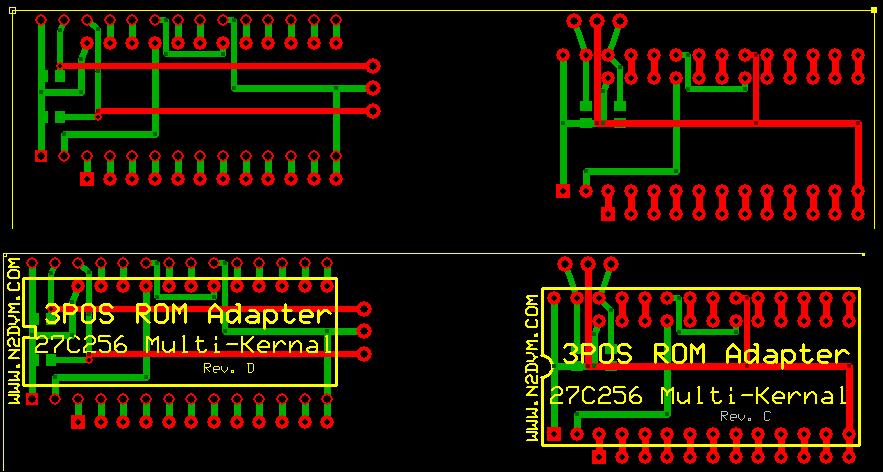
Kernal ROM Board
04:11 2/20/2010
Easy flash carts (5x) arrived today, Sorry, No pics. Battery died in the camera. :( Don't know what an "Easyflash" cart is? Go here, www.for8bits.com and find out. I'm going to try and build one today when I get time. I have to work. Gotta work to buy toys..
03:41 2/15/2010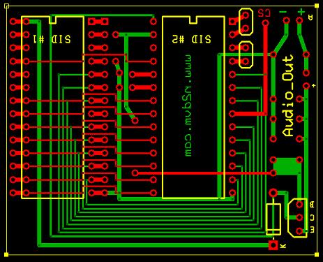
I'm still working on this so it's by no means COMPLETE...
17:17 2/14/2010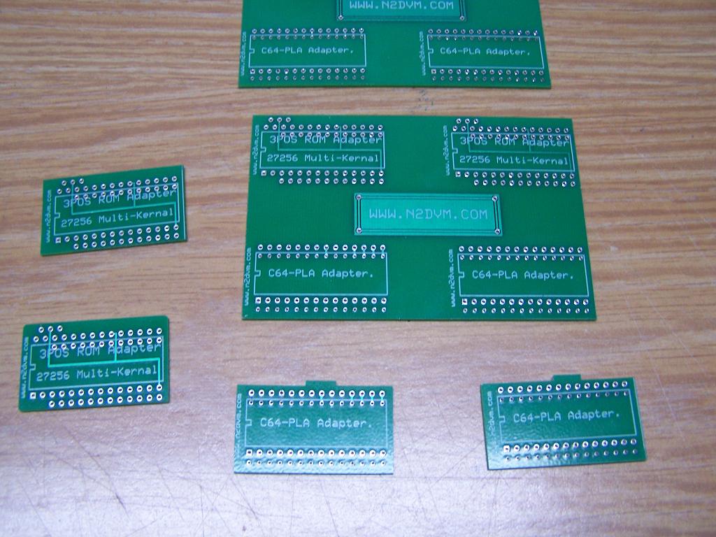
Rev B board. Fixed a few mistakes I made, Board still worked though.