 ----- The N2DVM BLOG of projects and what not. -----
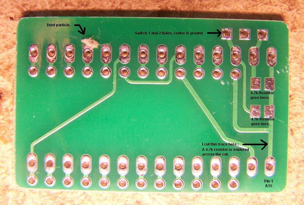
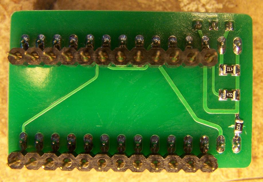
The other day I got an email from a gent in Italy wanting a 5 kernel adapter, MAX I've ever done was 4 using my C64 kernel 24 to 28 pin adapter boards using 2 switches. After some thought I decided to pull out all my notes, EPROM pin out sheets and a C64 kernel blank PCB. I looked those over for awhile and had an idea in mind to try, I made some notes of my ideas while they were fresh in my head because if I don't do that I get side tracked easily and forget what my idea was. Call it adult A.D.D or what ever you want LOL. When I got home from work I fired up the soldering iron to make the needed changes to the C64 kernel PCB that were needed to make a 27512 - 64K EPROM work in it. The original design was for a 27256 - 32K EPROM max. In order to access the higher banks of the 27512 EPROM I need to cut the trace to Pin 1 - (A15) on the PCB and then solder a pull up resistor (4.7k) across that same gap. The next thing was to connect a 3rd switch to allow access to those extra four 8k banks of ROM. With this setup I'm able to have 8 different Kernels on one EPROM.
I got to work assembling the needed 64k binary file that had the 8 - 8k kernels in it to program to the 27512 EPROM that I was going to use in the adapter. The current layout is assembled like this :
_______________________________1__2__3__
1 - 0000-1FFF - Turbo Trans - on/on/on
2 - 2000-3FFF - SX64 - on/off/on
3 - 4000-5FFF - Turbo Disk - off/on/on
4 - 6000-7FFF - ProLogic - off/off/on
5 - 8000-9FFF - Stock64 - on/on/off
6 - A000-BFFF - PiffyDOS - on/off/off
7 - C000-DFFF - SpeedDos - off/on/off
8 - E000-FFFF - Exos - off/off/off
Switch 1 = A13
Switch 2 = A14
Switch 3 = A15
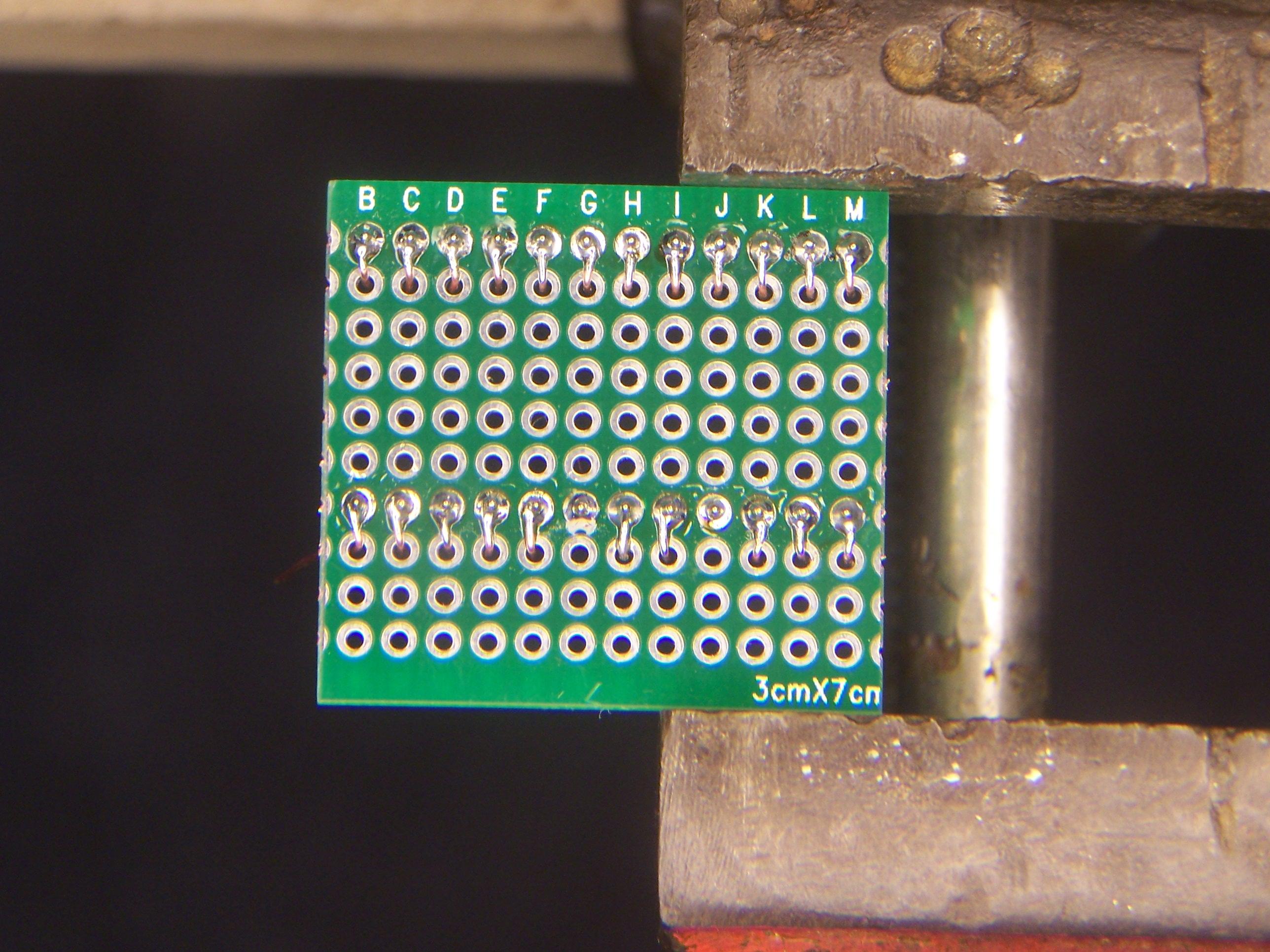
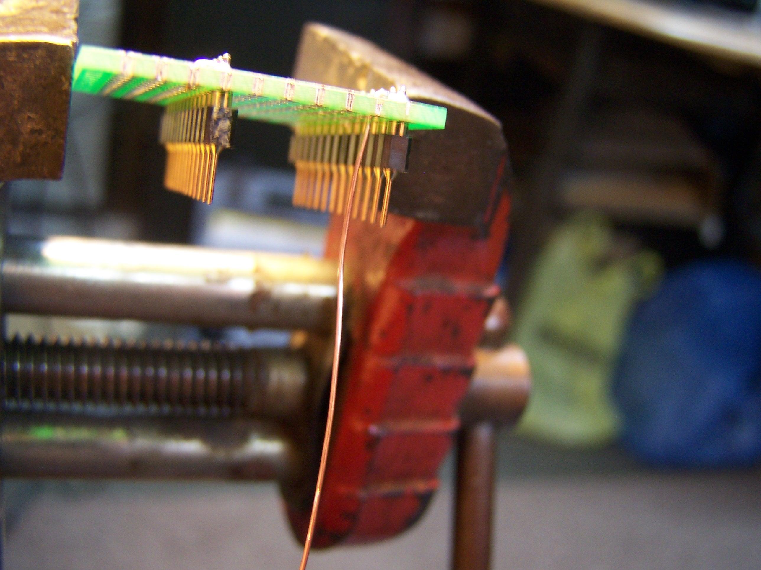
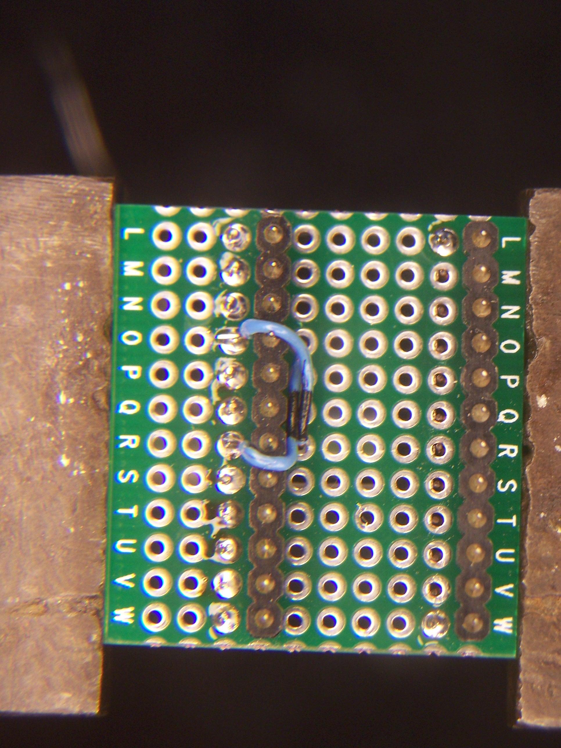
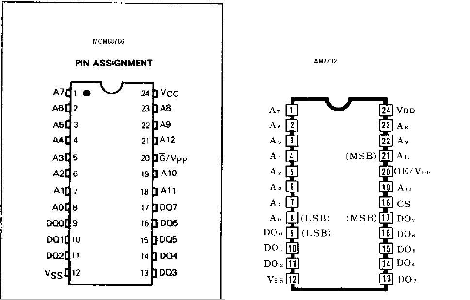
A friend of mine (goog on IRC) had told me he made a custom character ROM for his C64. I asked how and he told me he used a custom character set he created and an MCM68766 24 pin 8K EPROM. That EPROM has the exact same pinout as the original character ROM does. All I had on hand were a few AMD AM2732 24 pin 4K EPROMS. The pinouts are not the same. Pins 18 and 21 are different so you can't just drop one of these AMD EPROMS in after programming.... well you can BUT you will only see one character set and the other will be all screwed up, I know I tried it anyways. As the pins were different I needed to make some kind of adapter. I didn't want to use a stack of sockets to do what needed to be done. I decided to use one of the man thru hole circuit boards I purchased on eBay awhile back just for this type of project. They are a double sided type board. Next up was how to wire the board so the socket was wired to the pin headers. I decided to use some of that solid phone wire I had in the wire box. I also used one of those cheap sockets that has the real thin legs on them. I bent the wire in a small "L" shape with just enough length to go thru the hole next to each of the pin header legs and then snip it of on the back side of the board. What this did was allow the wire AND the leg from the IC socket to be in the SAME HOLE to make the connections after I soldered the socket in. It was a bit of a pain to solder 22 times like that BUT it worked and I'm happy with it. You can see from one of the pictures, the wire and the IC socket leg on the PCB that I later soldered. (Picture on the right) I would have soldered in the EPROM but at the time I didn't even know if it was going to work and only have a couple of the 4K eproms I really didn't have one to spare so to speak. When I tried it all the characters were screwed up, I almost tossed it in the trash. I looked at the pinouts and realized that Pin 18 on the EPROM shouldn't be connected (The Blue/Black wire connected to the Pin with the "R" ). I removed the wire and tested again, BINGO it worked and here is the Blog entry about it. :) Pin 21 on the EPROM is connected to the SOCKET Pin 18 that connects to the C64 main board.
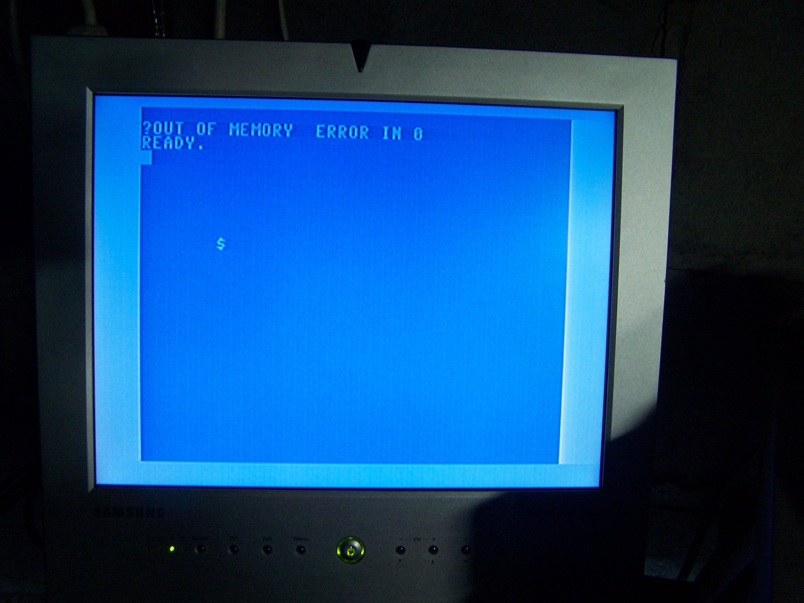
Have you ever seen that dreaded message "Out of memory error in 0" ? Well I seen it for the first time on a board I was given by my friend Alan. Yet another problem to solve that I've never worked on before. Actually the board had 3 problems when I got it. I was given seven C64s as parts but looking for a challenge I decided to try and start fixing them. This board started out with no video and the power switch was bad. The first thing I did was replace the VIC chip, guess what I had video and thats when I seen the "Out of memory error in 0" message. Before I started working on the memory problem I wanted to replace the power switch. I have a couple here that I pulled out of boards that already had parts stripped. With the power switch replaced I started hunting down the memory problem. Of course I tried the "HEAT Test" but that failed on me. I left the board powered up for about a half hour, none of the memory chips got warm/hot so that did't help me out. In the end it was the U22 memory IC that was bad.
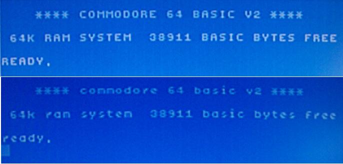
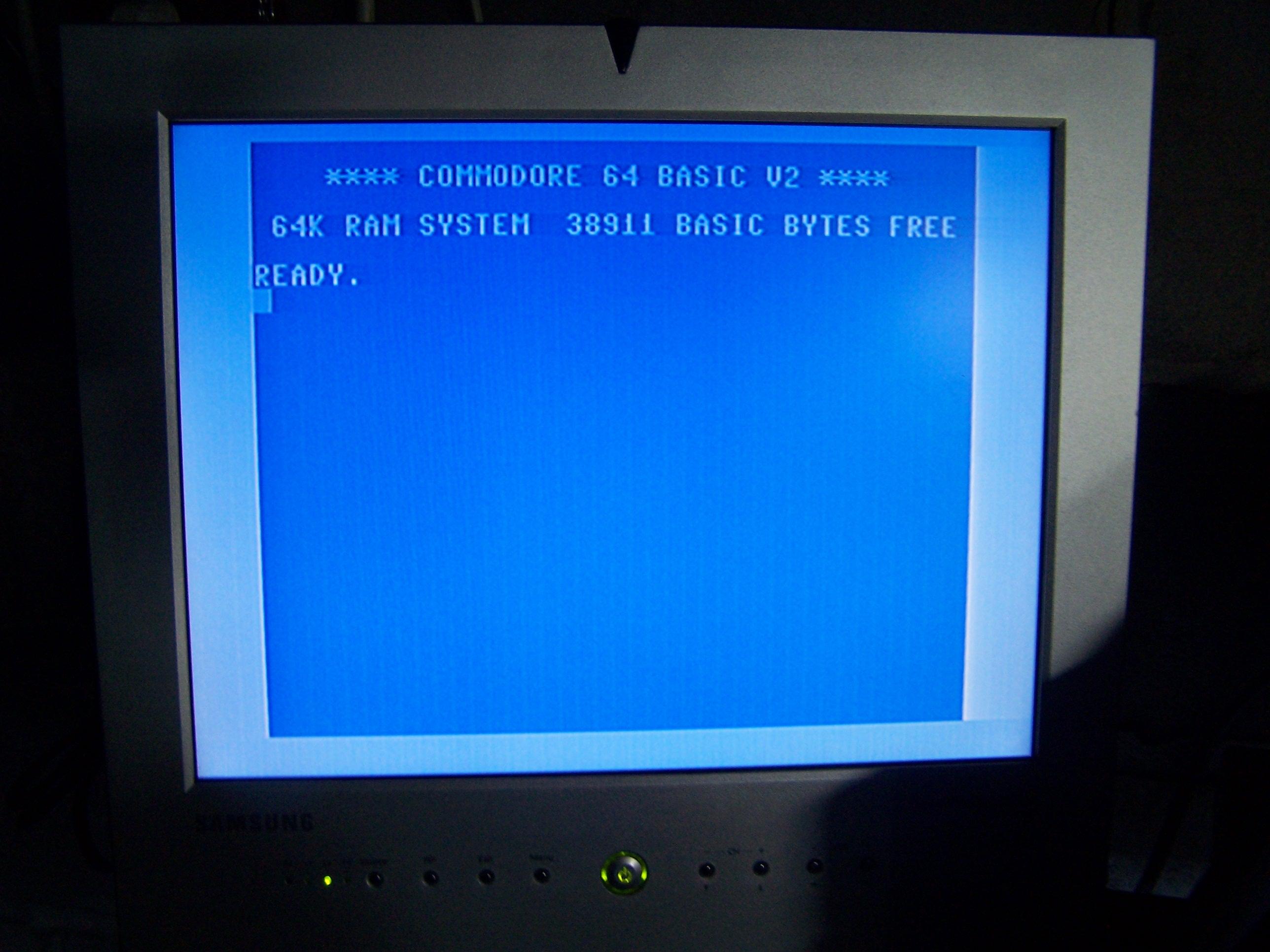
I was reading thru the book "Troubleshooting & Repairing your Commodore 64". In that book they talk about how a lot of the systems in the 64 work, check it out. Below are the before and after screens. I gotta say, the video looks way better than the two other 64s I use. I just might have to switch out the boards in one of them heh.
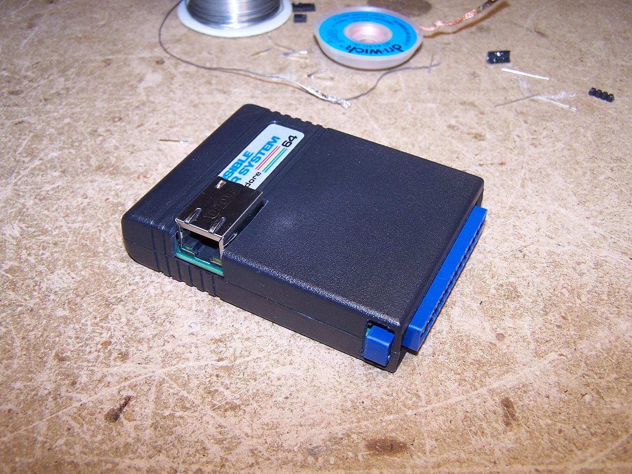
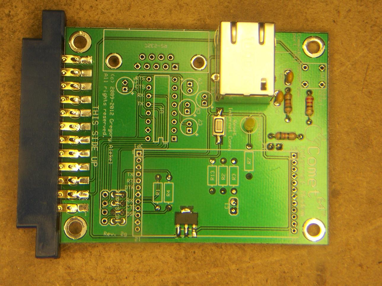
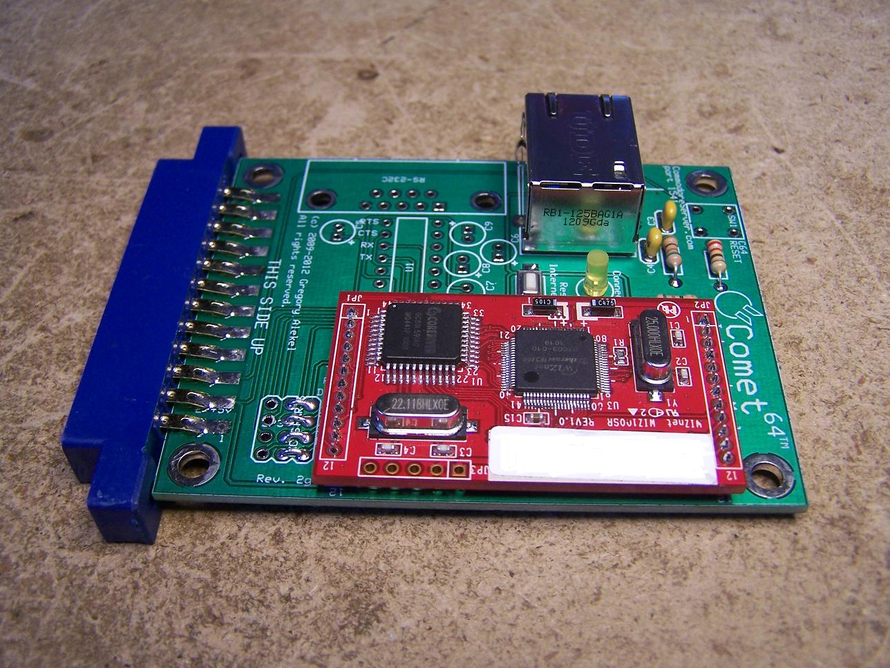
I finally decided to put my Comet into a Commodore cartridge case. The board is a perfect size to put into a cart case with a little trimming here and there on the inside of the cart case. After a little bit of figuring out how I wanted to cut the opening for the ethernet connector I went ahead and cut that out, not a perfect job but not all that bad either. Looks good to me. The next thing was, I didn't want to cut the ears off the user port connector so I just cut the openings into the sides of the case, problem solved!!
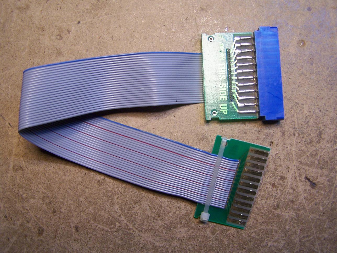
The next thing to do was to LOWER the Wiznet board so the case would close. First thing I did was remove the pin headers, that took a bit of work as I didn't want to destroy it. A new one was $22. after I did that, there were 6 resistors and 2 capacitors that needed to be moved but where..... AHH put them on the BOTTOM side of the board. After I did that the Wiznet board sat plenty low enough to close the case. What you see is the final product. I use the user port cable to connect the Comet to the computer, the cart case doesn't fit in the user port opening. Work perfect with no problems.

Happy New Year to every one.... oh wait it's Jan 29th... SEE I told you I've been slacking.
I really haven't been up to much C= related stuff other than using the Flyer and Comet devices on IRC. I don't want to pollute the BLOG with Non-Commodore related stuff.
I'm doing this entry to let everyone know that I'm still around and into Commodore.